- 1.1. Introduction
- 1.2. Components of the Petroleum Production System
- 1.3. Well Productivity and Production Engineering
- 1.4. Units and Conversions
- References
1.2. Components of the Petroleum Production System
1.2.1. Volume and Phase of Reservoir Hydrocarbons
1.2.1.1. Reservoir
The reservoir consists of one or several interconnected geological flow units. While the shape of a well and converging flow have created in the past the notion of radial flow configuration, modern techniques such as 3-D seismic and new logging and well testing measurements allow for a more precise description of the shape of a geological flow unit and the ensuing production character of the well. This is particularly true in identifying lateral and vertical boundaries and the inherent heterogeneities.
Appropriate reservoir description, including the extent of heterogeneities, discontinuities, and anisotropies, while always important, has become compelling after the emergence of horizontal wells and complex well architecture with total lengths of reservoir exposure of many thousands of feet.
Figure 1-1 is a schematic showing two wells, one vertical and the other horizontal, contained within a reservoir with potential lateral heterogeneities or discontinuities (sealing faults), vertical boundaries (shale lenses), and anisotropies (stress or permeability).
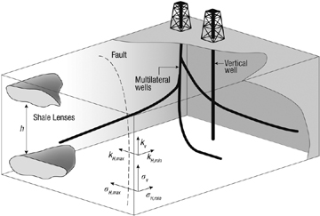
Figure 1-1. Common reservoir heterogeneities, anisotropies, discontinuities, and boundaries affecting the performance of vertical, horizontal, and complex-architecture wells.
While appropriate reservoir description and identification of boundaries, heterogeneities, and anisotropies is important, it is somewhat forgiving in the presence of only vertical wells. These issues become critical when horizontal and complex wells are drilled.
The encountering of lateral discontinuities (including heterogeneous pressure depletion caused by existing wells) has a major impact on the expected complex well production. The well branch trajectories vis à vis the azimuth of directional properties also has a great effect on well production. Ordinarily, there would be only one set of optimum directions.
Understanding the geological history that preceded the present hydrocarbon accumulation is essential. There is little doubt that the best petroleum engineers are those who understand the geological processes of deposition, fluid migration, and accumulation. Whether a reservoir is an anticline, a fault block, or a channel sand not only dictates the amount of hydrocarbon present but also greatly controls well performance.
1.2.1.2. Porosity
All of petroleum engineering deals with the exploitation of fluids residing within porous media. Porosity, simply defined as the ratio of the pore volume, Vp, to the bulk volume, Vb,
is an indicator of the amount of fluid in place. Porosity values vary from over 0.3 to less than 0.1. The porosity of the reservoir can be measured based on laboratory techniques using reservoir cores or with field measurements including logs and well tests. Porosity is one of the very first measurements obtained in any exploration scheme, and a desirable value is essential for the continuation of any further activities toward the potential exploitation of a reservoir. In the absence of substantial porosity there is no need to proceed with an attempt to exploit a reservoir.
1.2.1.3. Reservoir Height
Often known as “reservoir thickness” or “pay thickness,” the reservoir height describes the thickness of a porous medium in hydraulic communication contained between two layers. These layers are usually considered impermeable. At times the thickness of the hydrocarbon-bearing formation is distinguished from an underlaying water-bearing formation, or aquifer. Often the term “gross height” is employed in a multilayered, but co-mingled during production, formation. In such cases the term “net height” may be used to account for only the permeable layers in a geologic sequence.
Well logging techniques have been developed to identify likely reservoirs and quantify their vertical extent. For example, measuring the spontaneous potential (SP) and knowing that sandstones have a distinctly different response than shales (a likely lithology to contain a layer), one can estimate the thickness of a formation. Figure 1-2 is a well log showing clearly the deflection of the spontaneous potential of a sandstone reservoir and the clearly different response of the adjoining shale layers. This deflection corresponds to the thickness of a potentially hydrocarbon-bearing, porous medium.
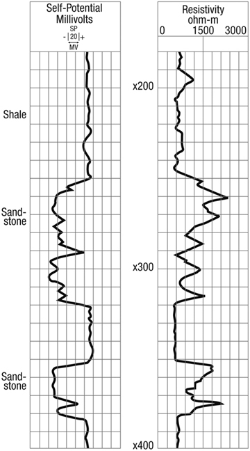
Figure 1-2. Spontaneous potential and electrical resistivity logs identifying sandstones versus shales, and water-bearing versus hydrocarbon-bearing formations.
The presence of satisfactory net reservoir height is an additional imperative in any exploration activity.
1.2.1.4. Fluid Saturations
Oil and/or gas are never alone in “saturating” the available pore space. Water is always present. Certain rocks are “oil-wet,” implying that oil molecules cling to the rock surface. More frequently, rocks are “water-wet.” Electrostatic forces and surface tension act to create these wettabilities, which may change, usually with detrimental consequences, as a result of injection of fluids, drilling, stimulation, or other activity, and in the presence of surface-acting chemicals. If the water is present but does not flow, the corresponding water saturation is known as “connate” or “interstitial.” Saturations larger than this value would result in free flow of water along with hydrocarbons.
Petroleum hydrocarbons, which are mixtures of many compounds, are divided into oil and gas. Any mixture depending on its composition and the conditions of pressure and temperature may appear as liquid (oil) or gas or a mixture of the two.
Frequently the use of the terms oil and gas is blurred. Produced oil and gas refer to those parts of the total mixture that would be in liquid and gaseous states, respectively, after surface separation. Usually the corresponding pressure and temperature are “standard conditions,” that is, usually (but not always) 14.7 psi and 60° F.
Flowing oil and gas in the reservoir imply, of course, that either the initial reservoir pressure or the induced flowing bottomhole pressures are such as to allow the concurrent presence of two phases. Temperature, except in the case of high-rate gas wells, is for all practical purposes constant.
An attractive hydrocarbon saturation is the third critical variable (along with porosity and reservoir height) to be determined before a well is tested or completed. A classic method, currently performed in a variety of ways, is the measurement of the formation electrical resistivity. Knowing that formation brines are good conductors of electricity (i.e., they have poor resistivity) and hydrocarbons are the opposite, a measurement of this electrical property in a porous formation of sufficient height can detect the presence of hydrocarbons. With proper calibration, not just the presence but also the hydrocarbon saturation (i.e., fraction of the pore space occupied by hydrocarbons) can be estimated.
Figure 1-2 also contains a resistivity log. The previously described SP log along with the resistivity log, showing a high resistivity within the same zone, are good indicators that the identified porous medium is likely saturated with hydrocarbons.
The combination of porosity, reservoir net thickness, and saturations is essential in deciding whether a prospect is attractive or not. These variables can allow the estimation of hydrocarbons near the well.
1.2.1.5. Classification of Reservoirs
All hydrocarbon mixtures can be described by a phase diagram such as the one shown in Figure 1-3. Plotted are temperature (x axis) and pressure (y axis). A specific point is the critical point, where the properties of liquid and gas converge. For each temperature less than the critical-point temperature (to the left of Tc in Figure 1-3) there exists a pressure called the “bubble-point” pressure, above which only liquid (oil) is present and below which gas and liquid coexist. For lower pressures (at constant temperature), more gas is liberated. Reservoirs above the bubble-point pressure are called “undersaturated.”
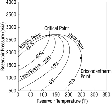
Figure 1-3. Oilfield hydrocarbon phase diagram showing bubble-point and dew-point curves, lines of constant-phase distribution, region of retrograde condensation, and the critical and cricondentherm points.
If the initial reservoir pressure is less than or equal to the bubble-point pressure, or if the flowing bottomhole pressure is allowed to be at such a value (even if the initial reservoir pressure is above the bubble point), then free gas will at least form and will likely flow in the reservoir. This type of a reservoir is known as “two-phase” or “saturated.”
For temperatures larger than the critical point (to the right of Tc in Figure 1-3), the curve enclosing the two-phase envelop is known as the “dew-point” curve. Outside, the fluid is gas, and reservoirs with these conditions are “lean” gas reservoirs.
The maximum temperature of a two-phase envelop is known as the “cricondentherm.” Between these two points there exists a region where, because of the shape of the gas saturation curves, as the pressure decreases, liquid or “condensate” is formed. This happens until a limited value of the pressure, after which further pressure reduction results in revaporization. The region in which this phenomenon takes place is known as the “retrograde condensation” region, and reservoirs with this type of behavior are known as “retrograde condensate reservoirs.”
Each hydrocarbon reservoir has a characteristic phase diagram and resulting physical and thermodynamic properties. These are usually measured in the laboratory with tests performed on fluid samples obtained from the well in a highly specialized manner. Petroleum thermodynamic properties are known collectively as PVT (pressure–volume–temperature) properties.
1.2.1.6. Areal Extent
Favorable conclusions on the porosity, reservoir height, fluid saturations, and pressure (and implied phase distribution) of a petroleum reservoir, based on single well measurements, are insufficient for both the decision to develop the reservoir and for the establishment of an appropriate exploitation scheme.
Advances in 3-D and wellbore seismic techniques, in combination with well testing, can increase greatly the region where knowledge of the reservoir extent (with height, porosity, and saturations) is possible. Discontinuities and their locations can be detected. As more wells are drilled, additional information can enhance further the knowledge of the reservoir’s peculiarities and limits.
The areal extent is essential in the estimation of the “original-oil (or gas)-in-place.” The hydrocarbon volume, VHC, in reservoir cubic ft is
where A is the areal extent in ft2, h is the reservoir thickness in ft, ϕ is the porosity, and Sw is the water saturation. (Thus, 1 – Sw is the hydrocarbon saturation.) The porosity, height, and saturation can of course vary within the areal extent of the reservoir.
Equation (1-2) can lead to the estimation of the oil or gas volume under standard conditions after dividing by the oil formation volume factor, Bo, or the gas formation volume factor, Bg. This factor is simply a ratio of the volume of liquid or gas under reservoir conditions to the corresponding volumes under standard conditions. Thus, for oil,
where N is in stock tank barrels (STB). In Equation (1-3) the area is in acres. For gas,
where G is in standard cubic ft (SCF) and A is in ft2.
The gas formation volume factor (traditionally, res ft3/SCF), Bg, simply implies a volumetric relationship and can be calculated readily with an application of the real gas law. The gas formation volume factor is much smaller than 1.
The oil formation volume factor (res bbl/STB), Bo, is not a simple physical property. Instead, it is an empirical thermodynamic relationship allowing for the reintroduction into the liquid (at the elevated reservoir pressure) of all of the gas that would be liberated at standard conditions. Thus the oil formation volume factor is invariably larger than 1, reflecting the swelling of the oil volume because of the gas dissolution.
The reader is referred to the classic textbooks by Muskat (1949), Craft and Hawkins (revised by Terry, 1991), and Amyx, Bass, and Whiting (1960), and the newer book by Dake (1978) for further information. The present textbook assumes basic reservoir engineering knowledge as a prerequisite.
1.2.2. Permeability
The presence of a substantial porosity usually (but not always) implies that pores will be interconnected. Therefore the porous medium is also “permeable.” The property that describes the ability of fluids to flow in the porous medium is permeability. In certain lithologies (e.g., sandstones), a larger porosity is associated with a larger permeability. In other lithologies (e.g., chalks), very large porosities, at times over 0.4, are not necessarily associated with proportionately large permeabilities.
Correlations of porosity versus permeability should be used with a considerable degree of caution, especially when going from one lithology to another. For production engineering calculations these correlations are rarely useful, except when considering matrix stimulation. In this instance, correlations of the altered permeability with the altered porosity after stimulation are useful.
The concept of permeability was introduced by Darcy (1856) in a classic experimental work from which both petroleum engineering and groundwater hydrology have benefited greatly.
Figure 1-4 is a schematic of Darcy’s experiment. The flow rate (or fluid velocity) can be measured against pressure (head) for different porous media.
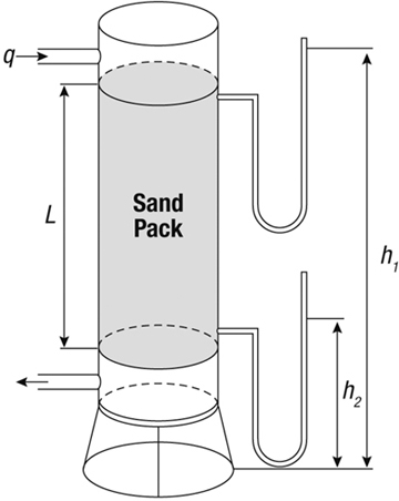
Figure 1-4. Darcy’s experiment. Water flows through a sand pack and the pressure difference (head) is recorded.
Darcy observed that the flow rate (or velocity) of a fluid through a specific porous medium is linearly proportional to the head or pressure difference between the inlet and the outlet and a characteristic property of the medium. Thus,
where k is the permeability and is a characteristic property of the porous medium. Darcy’s experiments were done with water. If fluids of other viscosities flow, the permeability must be divided by the viscosity and the ratio k/μ is known as the “mobility.”
1.2.3. The Zone near the Well, the Sandface, and the Well Completion
The zone surrounding a well is important. First, even without any man-made disturbance, converging, radial flow results in a considerable pressure drop around the wellbore and, as will be demonstrated later in this book, the pressure drop away from the well varies logarithmically with the distance. This means that the pressure drop in the first foot away from the well is naturally equal to that 10 feet away and equal to that 100 feet away, and so on. Second, all intrusive activities such as drilling, cementing, and well completion are certain to alter the condition of the reservoir near the well. This is usually detrimental and it is not inconceivable that in some cases 90% of the total pressure drop in the reservoir may be consumed in a zone just a few feet away from the well.
Matrix stimulation is intended to recover or even improve the near-wellbore permeability. (There is damage associated even with stimulation. It is the net effect that is expected to be beneficial.) Hydraulic fracturing, today one of the most widely practiced well-completion techniques, alters the manner by which fluids flow to the well; one of the most profound effects is that near-well radial flow and the damage associated with it are eliminated.
Many wells are cemented and cased. One of the purposes of cementing is to support the casing, but at formation depths the most important reason is to provide zonal isolation. Contamination of the produced fluid from the other formations or the loss of fluid into other formations can be envisioned readily in an open-hole completion. If no zonal isolation or wellbore stability problems are present, the well can be open hole. A cemented and cased well must be perforated in order to reestablish communication with the reservoir. Slotted liners can be used if a cemented and cased well is not deemed necessary and are particularly common in horizontal wells where cementing is more difficult.
Finally, to combat the problems of sand or other fines production, screens can be placed between the well and the formation. Gravel packing can be used as an additional safeguard and as a means to keep permeability-reducing fines away from the well.
The various well completions and the resulting near-wellbore zones are shown in Figure 1-5.
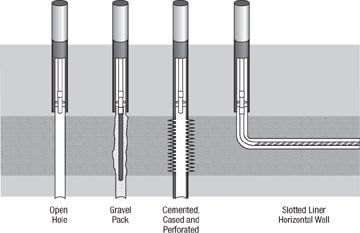
Figure 1-5. Options for well completions.
The ability to direct the drilling of a well allows the creation of highly deviated, horizontal, and complex wells. In these cases, a longer to far longer exposure of the well with the reservoir is accomplished than would be the case for vertical wells.
1.2.4. The Well
Entrance of fluids into the well, following their flow through the porous medium, the near-well zone, and the completion assembly, requires that they are lifted through the well up to the surface.
There is a required flowing pressure gradient between the bottomhole and the well head. The pressure gradient consists of the potential energy difference (hydrostatic pressure) and the frictional pressure drop. The former depends on the reservoir depth and the latter depends on the well length.
If the bottomhole pressure is sufficient to lift the fluids to the top, then the well is “naturally flowing.” Otherwise, artificial lift is indicated. Mechanical lift can be supplied by a pump. Another technique is to reduce the density of the fluid in the well and thus to reduce the hydrostatic pressure. This is accomplished by the injection of lean gas in a designated spot along the well. This is known as “gas lift.”
1.2.5. The Surface Equipment
After the fluid reaches the top, it is likely to be directed toward a manifold connecting a number of wells. The reservoir fluid consists of oil, gas (even if the flowing bottomhole pressure is larger than the bubble-point pressure, gas is likely to come out of solution along the well), and water.
Traditionally, the oil, gas, and water are not transported long distances as a mixed stream, but instead are separated at a surface processing facility located in close proximity to the wells. An exception that is becoming more common is in some offshore fields, where production from subsea wells, or sometimes the commingled production from several wells, may be transported long distances before any phase separation takes place.
Finally, the separated fluids are transported or stored. In the case of formation water it is usually disposed in the ground through a reinjection well.
The reservoir, well, and surface facilities are sketched in Figure 1-6. The flow systems from the reservoir to the entrance to the separation facility are the production engineering systems that are the subjects of study in this book.
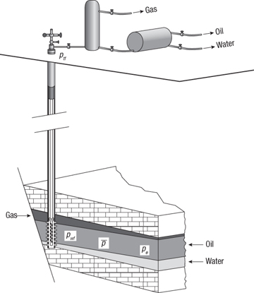
Figure 1-6. The petroleum production system, including the reservoir, underground well completion, the well, wellhead assembly, and surface facilities.


