- 5.1 Introduction
- 5.2 Pure Bending of Beams of Symmetrical Cross Section
- 5.3 Pure Bending of Beams of Asymmetrical Cross Section
- 5.4 Bending of A Cantilever of Narrow Section
- 5.5 Bending of a Simply Supported Narrow Beam
- 5.6 Elementary Theory of Bending
- 5.7 Normal and Shear Stresses
- 5.8 Effect of Transverse Normal Stress
- 5.9 Composite Beams
- 5.10 Shear Center
- 5.11 Statically Indeterminate Systems
- 5.12 Energy Method for Deflections
- 5.13 Elasticity Theory
- 5.14 Curved Beam Formula
- 5.15 Comparison of the Results of Various Theories
- 5.16 Combined Tangential and Normal Stresses
- References
- Problems
This chapter is from the book
This chapter is from the book
This chapter is from the book
Problems
Sections 5.1 through 5.5
5.1. A simply supported beam constructed of a 0.15 × 0.015 m angle is loaded by concentrated force P = 22.5 KN at its midspan (Fig. P5.1). Calculate stress σx at A and the orientation of the neutral axis. Neglect the effect of shear in bending and assume that beam twisting is prevented.
)
5.2. A wood cantilever beam with cross section as shown in Fig. P5.2 is subjected to an inclined load P at its free end. Determine (a) the orientation of the neutral axis and (b) the maximum bending stress. Given: P = 1 kN, α = 30°, b = 80 mm, h = 150 mm and length L = 1.2 m.
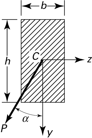
Figure P5.2.
5.3. A moment Mo is applied to a beam of the cross section shown in Fig. P5.3 with its vector forming an angle α. Use b = 100 mm, h = 40 mm, Mo = 800N·m, and α = 25°. Calculate (a) the orientation of the neutral axis and (b) the maximum bending stress.
)
5.4. Couples My = Mo and Mz = 1.5Mo are applied to a beam of cross section shown in Fig. P5.4. Determine the largest allowable value of Mo for the maximum stress not to exceed 80 MPa. All dimensions are in millimeters.
)
5.5. For the simply supported beam shown in Fig. P5.5, determine the bending stress at points D and E. The cross section is a 0.15 × 0.15 × 0.02 angle (Fig. 5.4).
)
5.6. A concentrated load P acts on a cantilever, as shown in Fig. P5.6. The beam is constructed of a 2024-T4 aluminum alloy having a yield strength σyp = 290 MPa, L = 1.5 m, t = 20 mm, c = 60 mm, and b = 80 mm. Based on a factor of safety n = 1.2 against initiation of yielding, calculate the magnitude of P for (a) α = 0° and (b) α = 15°. Neglect the effect of shear in bending and assume that beam twisting is prevented.
)
5.7. Re-solve Prob. 5.6 for α = 30°. Assume the remaining data are unchanged.
5.8. A cantilever beam has a Z section of uniform thickness for which  ,
, and Iyz = - th3. Determine the maximum bending stress in the beam subjected to a load P at its free end (Fig. P5.8).
)
5.9. A beam with cross section as shown in Fig. P5.9 is acted on by a moment Mo 3KN·m, with its vector forming an angle α = 20°. Determine (a) the orientation of the neutral axis and (b) the maximum bending stress.
5.10 and 5.11. As shown in the cross section in Figs. P5.10 and P5.11, a beam carries a moment M, with its vector forming an angle α with the horizontal axis. Find the stresses at points A, B, and D.
)
)
)
5.12. For the thin cantilever shown in Fig. P5.12, the stress function is given by
)
Determine the stresses σx,σy, and τxy by using the elasticity method.
Determine the stress σx by using the elementary method.
Compare the values of maximum stress obtained by the preceding approaches for L = 10h.
)
5.13. Consider a cantilever beam of constant unit thickness subjected to a uniform load of p = 2000 KN per unit length (Fig. P5.13). Determine the maximum stress in the beam:
Based on a stress function
Based on the elementary theory. Compare the results of (a) and (b).
)
)
Sections 5.6 through 5.11
5.14. A bending moment acting about the z axis is applied to a T-beam, as shown in Fig. P5.14. Take the thickness t = 15 mm and depth h = 90 mm. Determine the width b of the flange needed so that the stresses at the bottom and top of the beam will be in the ratio 3:1, respectively.
)
5.15. A wooden, simply supported beam of length L is subjected to a uniform load p. Determine the beam length and the loading necessary to develop simultaneously σmax = 8.4 MPa and τmax = 0.7 MPa Take thickness t = 0.05 m and depth h = 0.15 m.
5.16. A box beam supports the loading shown in Fig. P5.16. Determine the maximum value of P such that a flexural stress σ = 7 MPa or a shearing stress τ = 0.7 will not be exceeded.
)
5.17. Design a rectangular cantilever beam of constant strength and width b, to carry a uniformly distributed load of intensity w (Fig. P5.17). Assumption: Only the normal stresses due to the bending need be taken into account; the permissible stress equals σall.
)
5.18. Design a simply supported rectangular beam of constant strength and width b, supporting a uniformly distributed load of intensity w (Fig. P5.18). Assumption: Only the normal stresses due to the bending need be taken into account; the allowable stress is σall.
)
5.19. A steel beam of the tubular cross section seen in Fig. P5.19 is subjected to the bending moment M about the z axis. Determine (a) the bending moment M and (b) the radius of curvature rx of the beam. Given: σall = 150 MPa, E = 70 GPa, b = 120 mm, h = 170 mm, E = 70 GPa, b = 120 mm, h = 170 mm, and t = 10 mm.
)
5.20. An aluminum alloy beam of hollow circular cross section is subjected to a bending moment M about the z axis (Fig. P5.20). Determine (a) the normal stress at point A, (b) the normal stress at point B, and (c) the radius of curvature rx of the beam of a transverse cross section. Given: M = 600 N·m, D = 60 mm, d = 40 mm, E = 70 GPa, and v = 0.29.
)
5.21. A simply supported beam AB of the channel cross section carries a concentrated load P at midpoint (Fig. P5.21). Find the maximum allowable load P based on an allowable normal stress of σall = 60 MPa in the beam.
)
5.22. A uniformly loaded, simply supported rectangular beam has two 15-mm deep vertical grooves opposite each other on the edges at midspan, as illustrated in Fig. P5.22. Find the smallest permissible radius of the grooves for the case in which the normal stress is limited to σmax = 95 MPa. Given: p = 12 KN/m, L = 3, b = 80 mm, and h = 120 mm.
)
)
5.23. A simple wooden beam is under a uniform load of intensity p, as illustrated in Fig. P5.23. (a) Find the ratio of the maximum shearing stress to the largest bending stress in terms of the depth h and length L of the beam. (b) Using σall = 9 MPa,τall = 1.4 MPa, b = 50 mm and h = 160 mm, calculate the maximum permissible length L and the largest permissible distributed load of intensity p.
5.24. A composite cantilever beam 140 mm wide, 300 mm deep, and 3 m long is fabricated by fastening two timber planks, 60 mm × 300 mm, to the sides of a steel plate (Es = 200 GPa), 20 mm wide by 300 mm deep. Note that the 300-mm dimension is vertical. The allowable stresses in bending for timber and steel are 7 and 120 MPa, respectively. Calculate the maximum vertical load P that the beam can carry at its free end.
5.25. A simple beam pan length 3 m supports a uniformly distributed load of 40 kN/m. Find the required thickness t of the steel plates. Given: The cross section of the beam is a hollow box with wood flanges (Ew = 10.5 GPa) and steel (Es = 210 GPa), as seen in Fig. P5.25. Let a = 62.5 mm, b = 75 mm, and h = 225 mm. Assumptions: The permissible stresses are 140 MPa for the steel and 10 MPa for the wood.
)
5.26. A 180-mm-wide by 300-mm-deep wood beam (Ew = 10 GPa), 4 m long, is reinforced with 180-mm-wide and 10-mm-deep aluminum plates (Ea = 70 GPa) on the top and bottom faces. The beam is simply supported and subject to a uniform load of intensity 25 kN/m over its entire length. Calculate the maximum stresses in each material.
5.27. Referring to the reinforced concrete beam of Fig. 5.17a, assume b = 300, d = 450 mm, As = 1200 m2 and n = 10. Given allowable stresses in steel and concrete of 150 and 12 MPa, respectively, calculate the maximum bending moment that the section can carry.
5.28. Referring to the reinforced concrete beam of Fig. 5.17a, assume b = 300 mm, d = 500 mm, and n = 8. Given the actual maximum stresses developed to be σs = 80 MPa and σc = 5 MPa, calculate the applied bending moment and the steel area required.
5.29. A channel section of uniform thickness is loaded as shown in Fig. P5.29. Find (a) the distance e to the shear center, (b) the shearing stress at D, and (c) the maximum shearing stress. Given: b = 100 mm, h = 90 mm, t = 4 mm, Vy = 5 kN.
)
5.30. A beam is constructed of half a hollow tube of mean radius R and wall thickness t (Fig. P5.30). Assuming t ≪ R, locate the shear center S. The moment of inertia of the section about the z axis is Iz = πR3tl2.
)
5.31. An H-section beam with unequal flanges is subjected to a vertical load P (Fig. P5.31). The following assumptions are applicable:
The total resisting shear occurs in the flanges.
The rotation of a plane section during bending occurs about the symmetry axis so that the of curvature of both flanges are equal.
)
Find the location of the shear center S.
)
5.32. Determine the shear center S of the section shown in Fig. P5.32. All dimensions are in millimeters.
5.33. A cantilever beam AB supports a triangularly distributed load of maximum intensity po (Fig. P5.33). Determine (a) the equation of the deflection curve, (b) the deflection at the free end, and (c) the slope at the free end.
)
5.34. The slope at the wall of a built-in beam (Fig. P5.34a) is as shown in Fig. P5.34b and is given by PL3/96EI. Determine the force acting at the simple support, expressed in terms of p and L.
)
5.35. A fixed-ended beam of length L is subjected to a concentrated force P at a distance c away from the left end. Derive the equations of the elastic curve.
5.36. A propped cantilever beam AB is subjected to a couple Mo acting at support B, as shown in Fig. P5.36. Derive the equation of the deflection curve and determine the reaction at the roller support.
)
5.37. A clamped-ended beam AB carries a symmetric triangular load of maximum intensity p0 (Fig. P5.37). Find all reactions, the equation of the elastic curve, and the maximum deflection, using the second-order differential equation of the deflection.
)
5.38. A welded bimetallic strip (Fig. P5.38) is initially straight. A temperature increment ΔT causes the element to curve. The coefficients of thermal expansion of the constituent metals are α1 and α2. Assuming elastic deformation and α2 > α determine (a) the radius of curvature to which the strip bends, (b) the maximum stress occurring at the interface, and (c) the temperature increase that would result in the simultaneous yielding of both elements.
)
Sections 5.12 through 5.16
5.39. Verify the values of α for cases B, C, and D of Table 5.2.
5.40. Consider a curved bar subjected to pure bending (Fig. 5.24). Assume the stress function

Re-derive the stress field in the bar given by Eqs. (5.67).
5.41. The allowable stress in tension and compression for the clamp body shown in Fig. P5.41 is 80 MPa. Calculate the maximum permissible load that the member can resist. Dimensions are in millimeters.
)
5.42. A curved frame of rectangular cross section is loaded as shown in Fig. P5.42. Determine the maximum tangential stress (a) by using the second of Eqs. (5.67) together with the method of superposition and (b) by applying Eq. (5.73). Given: h = 100 mm,  , and P = 70 kN.
)
5.43. A curved frame having a channel-shaped cross section is subjected to bending by end moments M, as illustrated in Fig. P5.43. Determine the dimension b required if the tangential stresses at points A and B of the beam are equal in magnitude.
)
5.44. A curved beam of a circular cross section of diameter d is fixed at one end and subjected to a concentrated load P at the free end (Fig. P5.44). Calculate (a) the tangential stress at point A and (b) the tangential stress at point B. Given: P = 800 N, d = 20 mm, a = 25 mm, and b = 15 mm.
)
)
5.45. A circular steel frame has a cross section approximated by the trapezoidal form shown in Fig. P5.45. Calculate (a) the tangential stress at point A and (b) the tangential stress at point B. Given: ri = 100 mm, b = 75 mm, b = 50 mm, and P = 50 kN.
5.46. The triangular cross section of a curved beam is shown in Fig. P5.46. Derive the expression for the radius R along the neutral axis. Compare the result with that given for Fig. D in Table 5.3.
)
5.47. The circular cross section of a curved beam is illustrated in Fig. P5.47. Derive the expression for the radius R along the neutral axis. Compare the result with that given for Fig. B in Table 5.3.
)
5.48. The trapezoidal cross section of a curved beam is depicted in Fig. P5.48. Derive the expression for the radius R along the neutral axis. Compare the result with that given for Fig. E in Table 5.3.
)
5.49. A machine component of channel cross-sectional area is loaded as shown in Fig. P5.49. Calculate the tangential stress at points A and B. All dimensions are in millimeters.
)
5.50. A load P is applied to an eye bar with rigid insert for the purpose of pulling (Fig. P5.50). Determine the tangential stress at points A and B (a) by the elasticity theory, (b) by Winkler’s theory, and (c) by the elementary theory. Compare the results obtained in each case.
)
5.51. A ring of mean radius  and constant rectangular section is subjected to a concentrated load (Fig. P5.51). You may omit the effect of shear in bending. Derive the following general expression for the tangential stress at any section of the ring:
)
)
)
)
)
)
where

Use Castigliano’s theorem.
5.52. The ring shown in Fig. P5.51 has the following dimensions:  , t = 50 mm, and h = 100 mm. Taking
  , determine (a) the tangential stress on the inner fiber at θ = π/4 and (b) the deflection along the line of action of the load P, considering the effects of the normal and shear forces, as well as bending moment (Section 10.4).