VPN Services
The term VPN has different meanings for different groups of people; in general, a VPN is equated with interoffice connectivity or secure remote access. In a service provider environment, however, VPNs are virtually always synonymous with transport services aimed at providing separation between traffic from different source groups in an effort to transport them over a common underlying infrastructure. Figure 8-1 highlights the use of VPNs in a service provider environment, where traffic from different service types (such as residential, enterprise, and mobile) is transported over a single underlying infrastructure that provides a degree of separation. This separation ensures that each service type can receive differentiated treatment based on the agreement with the service provider.
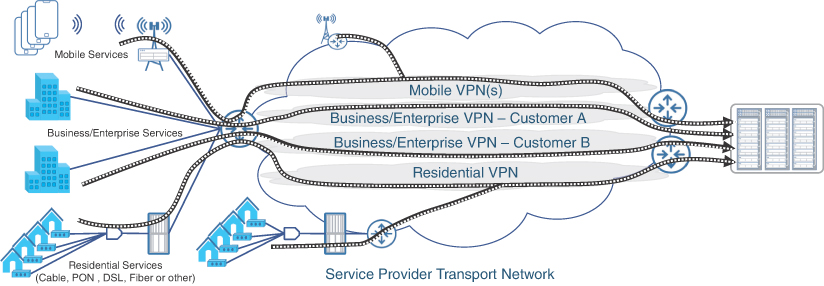
FIGURE 8.1 Service Isolation Using VPNs in Service Provider Networks
Using VPNs, the service provider can offer transport services for either Layer 3 (L3) or L2 traffic. When L3 traffic (IP) is transported over the service provider network, the service is called L3VPN, whereas L2VPN refers to a VPN service capable of transporting L2 frames. With Ethernet replacing older L2 technologies such as ATM and Frame Relay, modern L2VPN refers to the mechanism used to transport Ethernet traffic over an IP or MPLS transport underlay. Over the years, L2VPN technologies have been an area of extensive innovation. Traditionally, L2VPN services were implemented to provide an alternative to point-to-point leased lines, later evolving into multipoint Layer 2 technologies. More recently, Ethernet VPN (EVPN) has emerged as the de facto replacement for traditional L2VPN technologies such as Ethernet over MPLS (EoMPLS). This section covers both the traditional L2VPN technologies as well as EVPN for L2 transport over an IP/MPLS-based infrastructure.
Traditional Layer 2 VPN Services
L2VPNs have been instrumental in providing mobile services in early MCNs. As covered in Chapter 2, “Anatomy of Mobile Communication Networks,” and Chapter 3, “Mobile Networks Today,” pre-4G mobile networks required connectivity only between base stations (that is, cell sites) and their controllers (base station controllers in the case of 2G or radio network controllers in 3G). These controllers typically resided in the central office (that is, a regional or central DC), and their connection to the cell sites was initially achieved through the use of Frame Relay over T1/E1 links. As the transport networking technologies evolved in the 1990s and early 2000s, ATM started competing with Frame Relay for this connectivity. By the time 4G started gaining traction, the de facto standardization of Ethernet and MPLS over IP as the transport technology of choice made L2VPNs over MPLS the dominant technology for mobile transport.
Point-to-point L2VPN continued to be the predominant connectivity mechanism from the cell sites to the central office; however, the use of X2 interfaces in 4G (that is, connections between cell sites) introduced point-to-multipoint communication into the mobile backhaul. While L3VPNs are better suited for multipoint connectivity and are preferred for mobile transport networks, L2VPNs are still used in certain cases. One such example is the connectivity between the RU and DU in the case of decomposed RAN deployments. At the time of this writing, almost all implementations of RU and DU require L2 connectivity, which is implemented using traditional L2VPN or, relatively newer, Ethernet VPN (EVPN). This section covers the technical fundamentals of implementing point-to-point and multipoint traditional L2VPNs, whereas the next section will cover EVPN.
Point-to-Point L2VPN Services
Various different industry terminologies are used to describe the functionality provided by point-to-point L2VPN services. In the MEF ecosystems, point-to-point L2PVNs are called Ethernet Line (E-Line) services, whereas earlier IETF RFCs called this functionality Pseudo-Wire Emulation Edge-to-Edge (PWE3), or simply a pseudowire.1 The terms virtual circuit (VC) and pseudowire are also used interchangeably to define an L2VPN point-to-point circuit. Vendors also have been using their own terminologies to define the point-to-point L2VPN services. For instance, some Cisco implementations refer to point-to-point L2VPN as Any Transport over MPLS (AToM), signifying that in addition to Ethernet, other traffic types such as ATM and T1 could also be transported over an MPLS infrastructure.2 Other vendors, such as Nokia and Huawei, use the more generic Virtual Leased Line (VLL) terminology to refer to point-to-point L2VPN.3 Nokia further classifies its various L2VPN implementations as xPipe, where x can be substituted for the traffic type being transported in the L2VPN. For instance, ePipe, aPipe, or iPipe would refer to Nokia’s implementation of Ethernet, ATM, or IP transport over L2VPN, respectively.4 More recently, the industry as a whole has embraced virtual private wire services (VPWS) as the standard terminology when referring to point-to-point L2VPN services.
Ethernet has been the dominant L2 transport technology, and MPLS has been the de facto forwarding mechanism in large service provider networks. With this context, it comes as no surprise that Ethernet over MPLS (EoMPLS) has been the most widely used point-to-point L2VPN technology for several years. Effectively, EoMPLS works by encapsulating an Ethernet L2 PDU within an MPLS label (called the VPN label, Service label, or VC label) and forwarding the traffic over the underlying MPLS infrastructure. This VC label is unique to each individual EoMPLS pseudowire and is used to uniquely identify VPWS circuits. The L2VPN packet is typically encapsulated within another MPLS label, called the next-hop label or transport label, which identifies the forwarding path. In other words, almost all L2VPN traffic contains at least two MPLS labels: the inner label (VC label) that identifies the L2VPN circuit, and the outer label (transport label) that identifies the label switched path the traffic should take in the MPLS network.
The VC labels remain unchanged between the service endpoints, while the transport label might change due to the nature of MPLS-based forwarding where a label swap can occur at intermediary nodes. When the traffic is received on the penultimate hop, the outer label might be removed due to the penultimate hop popping (PHP) behavior and the remaining frame is forwarded toward the destination provider edge (PE) router with the inner label exposed. At the destination PE, this VC label identifies the L2VPN circuit and the attachment circuit associated with it. The attachment circuit is simply an Ethernet interface connecting the end device to the PE router providing the EoMPLS functionality. The VC label is then removed and the original Ethernet payload is forwarded over the attachment circuit, thus completing the L2VPN. Figure 8-2 shows the use of these inner and outer labels in a VPWS service.

FIGURE 8.2 Ethernet over MPLS (EoMPLS) Forwarding
The VC labels are unique to each VPWS, and the PE devices on either end of the pseudowire are responsible for imposing these labels. Although these imposed labels don’t have to match, both PE devices must be aware of each other’s VC label in order for the EoMPLS pseudowire to be established. These VC labels can be configured statically on both PE devices or dynamically allocated and exchanged during the pseudowire setup process. Multiple competing IETF RFCs exist that define the protocols used for dynamic VC label allocation and propagation. One of the earlier standards, RFC 4906, prescribes the use of Label Distribution Protocol (LDP) to assign and distribute VC labels. LDP is already used to exchange transport labels between adjacent routers in MPLS-LDP environments. Because the endpoints of an EoMPLS PW typically are multiple hops away, RFC 4906 proposes a mechanism to establish a Targeted LDP (T-LDP) session between nonadjacent MPLS routers.5 This T-LDP session is in addition to the already existing LDP sessions an MPLS-LDP-enabled router would establish with its directly connected neighbors. RFC 4906 was based on an IETF draft co-authored by Luca Martini of Level 3 Communications (later joined Cisco Systems), and as such the T-LDP-based EoMPLS is also commonly referred to as draft-martini.
The other mechanism for VC label exchange was documented in RFC 6624 and RFC 4761, both of which propose the use of Border Gateway Protocol (BGP) for L2VPN signaling and discovery.6, 7 These RFCs enhance BGP by introducing a new L2VPN address family to exchange L2VPN information between the PE routers. Using this new address family, the MPLS PE routers could automatically discover and signal the establishment of L2 pseudowires. BGP-based L2VPN signaling and auto-discovery was first proposed by Juniper Network’s Kireeti Kompella, and thus BGP-based L2VPN implementations were commonly called draft-kompella.
Cisco originally favored draft-martini, which popularized T-LDP-based EoMPLS implementations. Cisco later joined Juniper Networks in drafting the RFCs supporting BGP-based L2VPN auto-discovery and signaling mechanisms based on draft-kompella. Today, most if not all networking equipment manufacturers support both the draft-kompella and draft-martini implementations for L2VPN services.
The use of LDP in transport networks has been steadily declining over the past several years for many reasons (as discussed in Chapter 6, “Emerging Technologies for 5G-Ready Networks: Segment Routing”) and being substituted with Segment Routing (SR). Because SR deprecates the use of LDP for transport label exchange, the VC label signaling can’t happen over T-LDP and can only be exchanged using BGP, or configured statically. When using statically defined VC labels, the EoMPLS pseudowire is colloquially called static pseudowire and is supported by most networking equipment vendors.
Due to the simplicity, ease of deployment, and effectiveness of VPWS services, point-to-point L2VPNs are by far the most widely deployed L2VPN in service provider networks—mobile and otherwise. The VPWS service is always configured between two endpoints and, thus, traffic is not flooded to other devices as it would in a flat L2 network. As such, there is no need for MAC learning and address table lookups, saving precious memory space. VPWS services can be port-based (that is, all traffic from an attachment circuit is transported over the pseudowire) or VLAN-based, where every individual VLAN on the attachment circuit can be assigned its own VPWS pseudowire.
Point-to-point L2VPN services do have some drawbacks, however, particularly around scalability and redundancy of the pseudowires. In larger networks, with tens or hundreds of thousands of cell sites, the number of pseudowires required to provide connectivity from each cell site router to the central DC can push the scalability boundaries of the device(s) at the hub locations. The two endpoints of the pseudowire—the CSR and the terminating router, possibly a DCI or DC border leaf—represent single points of failure for the service. Cell sites typically rely on a single CSR, but, as a best practice, the router on the other end of the VPWS service is typically deployed in pairs.
By definition, a point-to-point pseudowire can only be established between the CSR and only one of the remote routers, raising redundancy concerns. To address this concern, EoMPLS allows the use of a backup pseudowire, where a CSR establishes a primary or an active pseudowire to one of the remote nodes, while at the same time establishing a backup pseudowire to the second one. In case of a primary node failure causing the active pseudowire to go down, the backup pseudowire assumes an active role and starts forwarding traffic, thus allowing service continuity. Figure 8-3 illustrates this concept of an active-backup pseudowire. While this solves the redundancy challenge, only one of two pseudowires can be used at any given time, thus reducing overall efficiency and scalability. Ethernet VPN, discussed later in this chapter, is one of the newer technologies that addresses this concern and offers an All-Active multi-homing solution for VPWS.
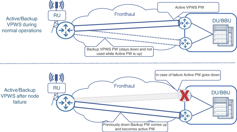
FIGURE 8.3 VPWS Redundancy Through Active-Backup Pseudowires
Multipoint L2VPN Services
Point-to-point L2VPN services are effective and easy to implement, but as previously indicated, these can present both device and architectural scale challenges should a large number of VPWS pseudowires converge on a single endpoint. Device scalability issues arise from the total number of discrete pseudowires the endpoint would need to support, whereas architectural scalability results from the network-wide resource usage, such as VLANs that might be required for each of those pseudowires. In some cases, it can be beneficial to terminate all the spoke pseudowires (that is, the pseudowires coming from multiple access locations) into a single bridge domain on the destination endpoint, thus creating a virtual hub-and-spoke topology.
A bridge domain is an indispensable element of any multipoint L2 service that represents a virtual construct within a PE router, providing L2 traffic-switching and MAC-learning functions. In simplistic terms, a bridge domain could be thought of as a mini-L2 switch within the PE router itself that provides traffic switching between its many interfaces. In the context of L2VPN, the interfaces associated with a bridge domain could be physical ports, Layer 2 subinterfaces, or pseudowires connecting to other PE devices. As such, a bridge domain provides traffic switching between L2 attachment circuits and pseudowires, as shown in Figure 8-4.
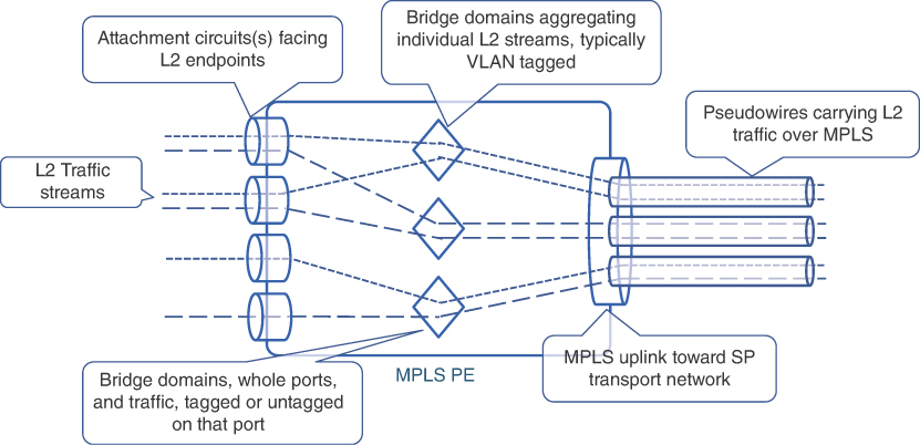
FIGURE 8.4 Bridge Domain Concepts
In a point-to-multipoint architecture, the bridge domain on the hub site router terminates pseudowires from multiple spoke routers—likely CSRs. While not decreasing the total number of pseudowires, the use of point-to-multipoint L2VPN simplifies the overall architecture by eliminating the need to maintain each pseudowire as a separate transport service. Additionally, terminating all the pseudowires on a single bridge domain on the hub site’s router simplifies the configuration required at the hub by possibly eliminating the need for a separate L2 construct (typically a L2 sub-interface) for each pseudowire. The bridge domain performs MAC learning to ensure traffic from the attachment circuit is forwarded over the correct pseudowire, although any broadcast traffic, multicast traffic, and unicast traffic to a destination with an unknown MAC address (collectively called BUM traffic) from the attachment circuit are expected to be sent over all the pseudowires terminating on that bridge domain. This behavior is indeed required to ensure that equipment at the hub site can communicate with the access nodes on the other end of the pseudowires.
On the other hand, to ensure that traffic from spoke nodes does not get sent to other spoke nodes, split horizon functionality can be implemented on the hub site where multiple pseudowires are terminated. Split horizon, in this case, allows traffic from any of the PE devices (that is, a pseudowire) to be sent only to the attachment circuit and not to other pseudowires, thus significantly reducing traffic flooding over the point-to-multipoint services. Return traffic from the attachment circuit is forwarded to the pseudowire based on the MAC address learned on the bridge domain. Metro Ethernet Forum refers to this hub-and-spoke, point-to-multipoint L2VPN implementation as an Ethernet Tree (E-Tree). Figure 8-5 shows a comparison between multiple VPWS and a single point-to-multipoint service.
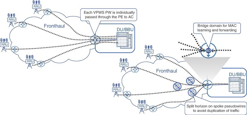
FIGURE 8.5 Point-to-Point and Point-to-Multipoint L2VPN Services
The E-Tree scenario outlined in Figure 8-5 is helpful where multiple spokes need to establish Layer 2 connections to a single hub site. This scenario is, however, not conducive to a truly multipoint communication where spokes would want to communicate with each other, in addition to the central locations. The any-to-any L2 connectivity, referred to as Ethernet LAN (E-LAN) by the Metro Ethernet Forum, was in fact a precursor to E-Tree. Multipoint E-LAN services have traditionally been implemented using Virtual Private LAN Services (VPLS), originally defined in RFC 4761 and RFC 4762. The two RFCs define the use of Kompella and Martini draft-based mechanisms in establishing in the individual pseudowires that make up a VPLS-based multipoint service.
Strictly speaking, VPLS is not a technology but rather an architecture that relies on participating PE routers to establish a full mesh of individual pseudowires among them to exchange L2 traffic. These pseudowires can be established using T-LDP session (RFC 4762) or BGP (RFC 4761) and, depending on the vendor’s implementation, are tied together through a combination of a VPLS instance and bridge domain. Juniper’s implementation uses the term VPLS Routing Instance, whereas Cisco calls its VPLS instance a Virtual Forwarding Interface (VFI). Whatever the case, each VPLS instance, configured on participating PE routers, identifies the network-wide multipoint L2VPN service and provides L2 traffic switching between PE routers and their respective attachment circuits. Because VPLS is typically implemented as a full-mesh architecture, loop avoidance becomes a key tenet of any viable VPLS implementation. As a rule of thumb, VPLS architecture, similar to E-Tree implementation (covered earlier), should not transmit traffic received from a PE (that is, from a pseudowire) to another PE (that is, to another pseudowire). Traffic from a pseudowire, even BUM traffic, should be forwarded only to an attachment circuit to avoid loops and traffic duplication within the L2VPN service. Typically, this behavior is the default implementation by major networking equipment vendors, but it does allow configuration tweaks to allow flexibility in design choices. One such design is the use of Hierarchical VPLS (H-VPLS), which circumvents the split-horizon rules to allow traffic to be passed between select pseudowires in an effort to create a more scalable multipoint L2VPN architecture.
While useful for multipoint L2 connectivity, the full-mesh implementation for VPLS results in an extremely high number of individual pseudowires in the network should the number of L2 endpoints grow beyond just a handful of PE devices. For instance, a six PE topology, such as that shown in Figure 8-6, requires 15 pseudowires to provide any-to-any full-mesh connectivity. Each of these 15 pseudowires have two endpoints (originating and terminating PE), and thus 30 configuration touchpoints. A network double its size (12 PE devices) would require more than four times as many (64) pseudowires, using the mathematical formula:
n*(n − 1)/2
where n is the number of PE devices.
Given these calculations, it is fairly obvious that a network with dozens or tens of dozens of L2 endpoints could result in an unmanageable number of VPLS pseudowires for each VPLS instance. If multiple VPLS instances are required, the result is an unfathomable number of total pseudowires that will test the scalability limits of individual devices as well as the network as whole. Another challenge with full-mesh VPLS implementations is the introduction of new L2 nodes or PE devices in an existing VPLS instance. Introducing a new PE in an VPLS instance is a network-wide disruption, where configuration changes might be required on all the existing PE devices to support the new pseudowires that need to be implemented.
H-VPLS offers a flexible and scalable alternative to the full-mesh VPLS topology by creating a two-level hierarchy of pseudowires. The core or aggregation devices implement the full mesh of pseudowires, as is typically done in a traditional VPLS implementation. The endpoints, or rather their associated PE routers in the access domain, then use a spoke pseudowire to connect to their closest aggregation or core PE. As the typical number of core and aggregation PEs is substantially lower than access PE devices, H-VPLS delivers a more scalable architecture that requires a lower number of total pseudowires. Split-horizon rules have to be tweaked in H-VPLS deployments to allow traffic forwarding between the spoke and core pseudowires. Network architects must ensure a loop-free topology in an H-VPLS architecture through careful split-horizon planning between core and spoke pseudowire. Figure 8-6 explains this further by highlighting the reduced number of pseudowires in an H-VPLS environment compared to a traditional VPLS architecture.
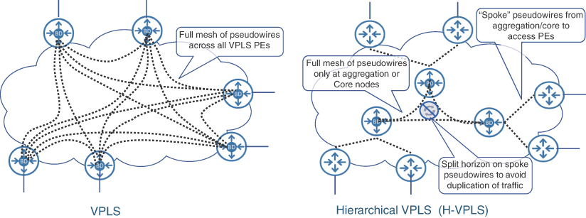
FIGURE 8.6 VPLS and Hierarchical VPLS (H-VPLS) Concepts
Multipoint L2VPN is an important tool in a network architect’s arsenal, but its applicability in MCN has been steadily decreasing over the past several years. This is because more and more endpoints are becoming “IP aware,” and thus most modern MCNs use Layer 3 VPNs as their primary transport mechanism. Pockets of MCNs, where RAN or mobile core devices might not be L3 aware, still rely on Layer 2 point-to-point or multipoint services, such as the RU-DU connectivity in the fronthaul, where L2 services are the only viable option currently. The rest of the xHaul transport uses L3VPNs, as also defined in the O-RAN’s xHaul Packet Switched Architecture Specifications.8
Layer 3 VPN Services
Commonly referred to as IP VPN or MPLS VPN, L3VPN services are some of the most successful, if not the most successful, transport services over the past few decades. L3VPNs have universal applications in both the service provider and enterprise sectors to achieve traffic separation and connectivity between multiple sites. While L2VPN provides Layer 2 (primarily Ethernet) connectivity over an MPLS network, L3VPN offers Layer 3 (usually IP) connectivity. With IP being the primary connectivity mechanism for various MCN components, mobile service providers extensively use L3VPNs within and across each MCN domain to enable end-to-end mobile services.
MPLS-based L3VPN is not precisely a new technology. In fact, the earliest IETF draft outlining MPLS VPN methods and functions dates back to the year 1998, and it was adopted as RFC 2547 in 1999.9 Since its introduction, MPLS VPN have gone through many updates defined in various RFCs, all aimed at enhancing its functionality and operations.
At its core, MPLS L3VPN enable a router to isolate and terminate a customer connection using a feature called Virtual Routing and Forwarding (VRF). A VRF is a Layer 3 construct within the MPLS PE that creates a separate routing and forwarding table. An MPLS PE supports multiple VRFs, thus providing a number of discrete customers their own routing table, thus segregating each customer’s routing. These VRF-specific routing tables are different from the default or global routing table and contain only the reachability information for specific VPNs. Each VRF also contains one or more interfaces, both physical and logical. Physical interfaces in the VRF are used to connect the provider’s PE device to the customer equipment.
Traffic received on interfaces belonging to a VRF can either be routed only to other interfaces that are part of the same VRF or sent to the remote VPN destinations using the routes in the VRF routing table. The VRF-specific routes are exchanged between MPLS PEs using Multi-Protocol BGPs (MP-BGP)—a term given to a collection of extensions and features that allows BGP to carry reachability information for multiple address families, including VPNv4, VPNv6, L2VPN, and EVPN, as well as the global IPv4/IPv6 routes. The routes exchanged for VPN are different from regular IPv4 routes in the sense that these are 12-byte entities instead of a regular 4-byte IP address. The additional 8 bytes come from a field called Route Distinguisher (RD) that is appended to every IPv4 route in the VRF, making it a VPN-IPv4 route, commonly called a VPNv4 route.10
The use of a unique RD for each VRF unlocks the possibility of IP address overlap between the multiple VRFs. In fact, one of the key benefits of L3VPN is the possibility of using the same IP addresses in the global routing table as well as in one or more VRFs, allowing the VPN customers to use any IP addresses for their endpoints, including private IP addresses, without worrying about IP address overlap with other customers. An RD has no discernable value in the MPLS VPN ecosystem other than uniquely distinguishing VPNv4 routes across multiple VRFs. Although entirely symbolic in nature, the RDs are transmitted as part of VPNv4 routes using MP-BGP. Figure 8-7 shows the MPLS BGP L3VPN concept across an SP network.
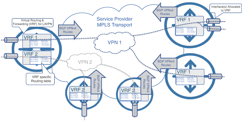
FIGURE 8.7 L3VPN Overview
Upon receiving the VPNv4 routes from remote MP-BGP peers, an MPLS PE populates its VRF-specific routing table based on the Route Target (RT), an 8-byte field that determines the VPN membership of a route, and can also be used for route filtering between multiple VPN sites. RTs are configured upon VRF creation and are exported with a VPNv4 route. These RTs are carried to other PE devices using MP-BGP Extended BGP Communities defined in RFC 4360.11 Upon receiving a VPNv4 route and its associated RT, the remote MPLS PE may choose to import the routes tagged with this RT into the VRF, thus populating the VRF-specific routing table. Multiple RTs, both for import and export, can be configured on a VRF and provide a simple yet powerful route-filtering mechanism in VPN-enabled networks.
Since its introduction in the late 1990s, MPLS-based L3VPNs have gone through a number of refinements and enhancements. One of the recent enhancements was the use of L3VPN with Segment Routing Traffic Engineering (SRTE) through route coloring and automated steering, as already discussed in Chapter 6. In fact, given the popularity and widespread use of MPLS-based L3VPNs, automated steering of L3VPN traffic into a Segment Routing policy was among the very first use cases to be implemented for SRTE.
L3VPNs are used extensively in today’s mobile communication networks. These VPN services are implemented not only to provide connectivity between various MCN domains, but also to ensure traffic isolation between mobile, fixed access, enterprise, and other services. Almost all mobile networks offer multigenerational services, where 2G and 4G are the most commonly offered services, with some providers still offering 3G services as well. In these scenarios, a separate L3VPN is typically used for each mobile generation. VPN services are also used to implement logical interfaces defined by 3GPP for connectivity between mobile components. For instance, X2 (for 4G) and Xn (for 5G) interfaces require inter-cell-site (or rather inter-eNB or inter-gNB) connectivity, which is usually implemented by using L3VPN.
Route targets, among other route-filtering techniques, play an important role in ensuring VPNs provide an appropriate level of connectivity. For instance, when all cell sites are part of the same VPN, it creates scalability challenges. To reiterate, cell site routers are typically smaller, relatively lower-cost devices with limited memory and CPU resources. Learning the IP or VPN routes of all other cell sites (often tens of thousands of sites) on a single CSR creates a significant scalability challenge. Xn (or X2) connections are typically required only between adjacent cell sites for handovers and advanced antenna functions such as multi-radio or coordinated multipoint transmissions. Route targets can prove useful here by filtering unwanted routes across the VPN PE devices. In the case of MCN, each RAN domain (that is, the collection of RAN sites in close vicinity) can export VPN routes tagged with a route target unique to that domain. Neighboring RAN domains can then import only the route with the desired route targets (typically only the neighboring RAN domains and the packet core), thus providing built-in route filtering. Central VPN sites, such as those connecting the mobile core to the VPN service, will need to import routes tagged with RTs from all the RAN domains in order to ensure connectivity between the mobile core and cell sites. These could be a significant number of routes, but the networking devices at the central sites are high-end routers that do not suffer from the same scalability challenges as a typical CSR, and are able to support a much higher route scale. Figure 8-8 shows an example use of L3VPNs in an MCN.
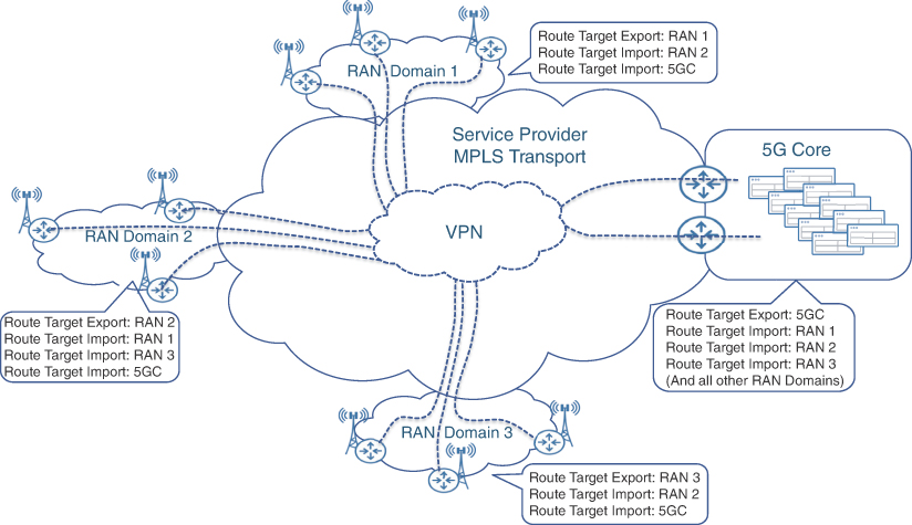
FIGURE 8.8 Route Targets Controlling VPN Route Distribution in an MCN
Ethernet VPN (EVPN)
The tremendous popularity and deployment success of both L2 and L3 VPN services over the last two decades did drive a lot of innovation and development work in both L2 and L3 technological camps. Although more and more end devices are steering away from L2-only connectivity and embracing the routable L3 approach, L2 services still play a vital role in modern MCNs and DCs. Indeed, not every communication flow can be easily retrofitted to use IP protocol stack, as this might require significant redesign of an end device’s hardware and software. Besides, there is common perception that the use of L2 simplifies redundancy and mobility of a service. In fact, there is a degree of truth in such perception. Applications in geo-redundant DCs often rely on L2 for load mobility, as migrating an IP flow in the backend of a DC can be a challenging task due to services disruption caused by reconfiguring IP addressing and routing. While the use of L2 technologies might simplify applications’ architecture, it usually does not reduce overall system complexity, but rather shifts it from applications to the network.
As discussed in the previous section of this chapter, L2VPN services do have their own set of challenges, such as scalability of MAC learning via a flood-and-learn approach and the lack of All-Active redundancy models, especially in point-to-point pseudowires. Ethernet VPN was introduced as an innovative solution to these challenges, as described in RFC 7432, “BGP MPLS-Based Ethernet VPN.”12
EVPN Concepts
The EVPN solution aims at providing optimizations in the areas of MAC address learning, BUM traffic handling, endpoint connection redundancy, as well as provisioning and deployment simplification. While the primary focus of EVPN is to provide L2VPN services, it also has the capability to transport L3 traffic. Most EVPN improvements required rethinking of the control plane, and, as such, the procedures defined by the EVPN standard predominantly deal with the control plane mechanisms. Unsurprisingly, MP-BGP was selected as the basis for EVPN, reusing the same Address Family Identifier (AFI) of 25, used by L2VPN services, with the new Subsequent Address Family Identifier (SAFI) of 70 defined specifically for EVPN.
The major difference between EVPN and traditional L2VPN technology is the exchange of MAC addresses learned by PE devices via the control plane. MAC learning in EVPN no longer uses the simplistic yet poorly scalable flood-and-learn method, but rather uses BGP to exchange information about MAC reachability. In other words, EVPN introduces the concept of routing of L2 packets across the transport network to their ultimate destination. For this purpose, EVPN uses Ethernet VPN Instance (EVI), Ethernet Segment Identifier (ESI), and a number of route types along with various attributes exchanged via BGP.
In essence, an EVI is a single EVPN service across the service provider network and consists of MAC-VRFs across all PE routers participating in that service. Each MAC-VRF is an instantiation of an individual VPN on a PE device, where instead of IP routing information, the VRF is populated with MAC addresses. A MAC-VRF can be implemented as a bridge domain associated with an EVI and performs L2 switching between local attachment circuits and EVPN peers.
Within the EVI, each connection from the PE to the end device is called an Ethernet segment, which is the equivalent of an attachment circuit in traditional L2VPN services. The end device in this case can be a host, a server, switch of even a router, and is using EVPN for L2 connectivity. In the case of an MCN, the end device might be an RU, DU, or other mobility-related component.
An Ethernet segment is not necessarily a single Ethernet link; it can be a link aggregation group (LAG) that might even span different PE devices. In the latter case, the end device is multi-homed to two or more PE devices, and all links connecting the same end device are considered to be the same Ethernet segment. These multi-homed links can be operating in Single-Active (only one link used for forwarding, others being backup) or All-Active (all links forwarding simultaneously and load-balancing traffic) mode. Each Ethernet segment is represented by an Ethernet Segment Identifier (ESI), which is exchanged between PE devices providing multihoming. Different PE routers can discover that they are connected to the same Ethernet segment by examining the ESI exchanged in one of the EVPN BGP route types (Route Type 4). Figure 8-9 illustrates EVPN concepts, including the use of EVIs, Ethernet segments, and multihoming.
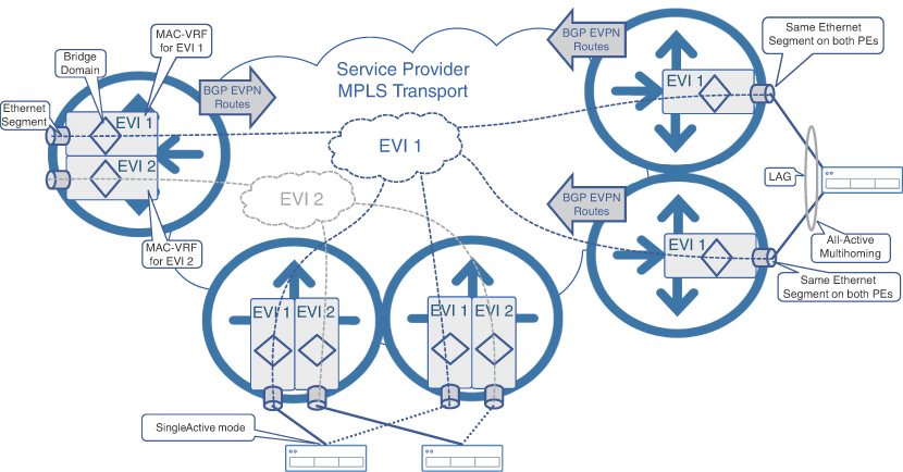
FIGURE 8.9 EVPN Concepts
EVPN Route Types
A number of EVPN BGP route types and special extended communities are used by EVPN PE devices to exchange information about EVPN instances, MAC addresses learned on Ethernet segments, labels, and other information required for EVPN operation. Five route types (1 through 5) have been standardized with a few more proposed by new IETF drafts at the time of this writing. These route types are covered here not in the order of their type number but rather based on their purpose.
EVPN Route Type 2
EVPN Route Type 2, or MAC/IP Advertisement Route, is the cornerstone of any multipoint EVPN service. PE devices use Type 2 routes to exchange information about learned as well as statically configured MAC addresses in their MAC-VRF. On each PE device, local MAC addresses are learned using the standard MAC learning process as L2 frames arrive on the Ethernet segment. As the MAC addresses are learned by the PE, it constructs a MAC/IP advertisement route and advertises it via BGP to other PE devices participating in the EVI, thus enabling remote MAC learning. This is in direct contrast to the traditional L2VPN approach where MAC addresses are learned via the data plane through the flood-and-learn approach. Each MAC/IP advertisement route relies on a set of route targets (RTs) to ensure remote PE devices import the route into the appropriate EVI. In a way similar to L3VPN, route distinguishers ensure uniqueness of BGP routes even if MAC/IP routes overlap in different EVIs. Interestingly enough, a MAC/IP advertisement route may carry the IP address of the end device as well; however, this information is used for ARP suppression rather than routing.
In a DC environment, especially with the use of virtual machines and containers, it is not uncommon for virtual entities to migrate to other servers within the same EVI, but connected to different PE devices. This results in their MAC address to be reachable from the new PE and thus requires every other PE in the network to learn about this MAC mobility. In order to support MAC mobility, a MAC/IP advertisement route relies on a MAC Mobility extended community defined specifically for this scenario. This extended community carries the sequence number, which is used to identify the latest version of the MAC/IP advertisement route and determine which PE should be used to deliver packets toward this MAC address.
EVPN Route Type 1
EVPN Route Type 1 is called Ethernet Auto-Discovery (A-D) Route and is advertised by PE routers per Ethernet segment and per EVI. Type 1 routes are used in fast convergence procedures and enable load balancing when end devices are multihomed to more than one PE device.
Indeed, without the A-D routes, the convergence can take substantially longer, as every MAC entry (learned using Type 2 routes) has to be individually timed out and replaced when an advertising PE fails. Instead, PE advertises an A-D route for an EVI/ESI along with its MAC/IP routes, thus creating a dependency between Type 2 and Type 1 routes. As a result, in the case of PE device or Ethernet segment failure causing a withdrawal of an A-D route, every MAC/IP route associated to that PE or Ethernet segment is withdrawn simultaneously. This process is also known as massive MAC withdrawal. This method is faster and more reliable than traditional L2VPN convergence, where a PE or attachment circuit failure simply means loss of traffic, and MAC entries are only updated via timeout or if traffic with the same MAC address is received through another path.
A-D routes are also fundamental for another EVPN key feature—All-Active multihoming. In an All-Active multihoming scenario, end devices connect to multiple PE routers, sharing the same EVI, and form a link aggregation group (LAG) spanning across these PE routers. The member links of the LAG are considered the same Ethernet segment by all participating PE devices and, thus, each PE advertises the A-D route for the common Ethernet segment. It is common for multihomed endpoints’ MAC addresses to be learned and advertised by only one PE, even though endpoints are multihomed to multiple PE devices. When a remote PE receives Type 2 MAC/IP routes and Type 1 A-D routes for the same Ethernet segment, it aliases all PE devices advertising these A-D routes to the set of MAC/IP routes. Therefore, aliasing enables load balancing of traffic for these MAC addresses across all available PE devices. Figure 8-10 illustrates aliasing and massive MAC withdrawal concepts.
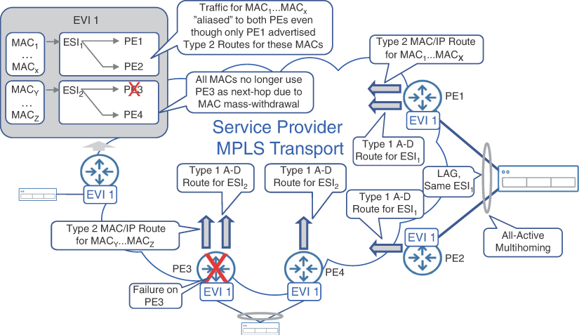
FIGURE 8.10 Aliasing and MAC Mass-Withdrawal in EVPN
When Single-Active multihoming is used, the traffic for learned MAC addresses is forwarded only to a preferred PE, also called a Designated Forwarder or DF. This is explained in detail later in this section. Other PE devices connected to the same Ethernet segment are used for forwarding only if the DF PE fails. Nevertheless, in the event of a single PE failure, it is not required to relearn all MAC/IP advertisement routes to start forwarding packets to backup PE devices. The aliasing of Type 2 MAC/IP routes to other PE devices via Type 1 A-D routes ensures faster switchover time in Single-Active multihoming scenarios as well. The desired redundancy mode used in multihoming (that is, single-active or all-active) is signaled by a flag in the ESI label extended community attached to an A-D route.
EVPN Route Type 4
EVPN Route Type 4 is an Ethernet segment route and is used for selection of a DF for the Ethernet segment in multihomed scenarios to avoid BUM traffic duplication toward an endpoint. When a BUM frame is transmitted over the network, every PE that is part of the same EVI receives a copy of it. Without a special mechanism, all PE devices would forward a copy of this BUM frame toward connected endpoints. This could result in a multihomed endpoint receiving multiple copies of the same BUM frame. To avoid this problem, PE devices on the same Ethernet segment select a single DF PE for their Ethernet segment. By exchanging Ethernet segment routes, PE devices discover common Ethernet segment connections and independently run a deterministic algorithm to identify which PE becomes a DF for a given Ethernet segment. Only the DF PE sends a copy of the BUM frames received from the network to the Ethernet segment, thus ensuring no duplicated frames on end devices. This behavior is shown on Figure 8-11.
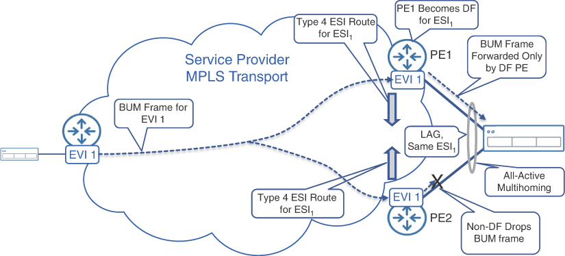
FIGURE 8.11 Designated Forwarder PE in EVPN
Although the introduction of DF PE solves the problem of BUM traffic duplication on the multihomed Ethernet segments, it does so only for BUM frames received from the network. The duplication problem can still occur in the reverse direction, when a BUM frame is received from a multihomed end device on an Ethernet segment. The hashing mechanism on the end device itself determines which PE would receive this BUM frame, and it can be either a DF PE or a non-DF PE.
If this BUM frame is received on the DF PE, it is then forwarded to all other PE devices sharing the same EVI over the MPLS network. Any non-DF PE connected to this Ethernet segment would also receive a copy of this BUM frame through the MPLS network. These PE devices will never forward it back to the same Ethernet segment because the non-DF PE is not allowed to forward any BUM frames received from the network to the Ethernet segment. No duplication occurs in this scenario.
In the second scenario, the BUM frame is received from a multihomed end device by a non-DF PE. Similar to the first scenario, the receiving PE (non-DF PE in this case) forwards this BUM frame over MPLS network to all other PE devices, but it inserts an additional label to identify the Ethernet segment it was received from. This label is advertised in the Type 1 A-D routes. When the BUM frame circles back over the MPLS network to the DF PE for the same Ethernet segment, the DF PE identifies the Ethernet segment via this label and never forwards it back the Ethernet segment, thus preventing frame echo. This is how EVPN implements split horizon. This mechanism applies only to DF PE devices connected to the originating Ethernet segment. The remote DF PE devices, connected to other Ethernet segments, follow the process shown in the Figure 8-11 and ignore the Ethernet segment identifier label.
EVPN Route Type 3
EVPN Route Type 3 is called the Inclusive Multicast Ethernet Tag route and provides a mechanism for PE devices to signal their interest in receiving BUM traffic for EVI as well as the required replication method. These replication methods could include an ingress PE performing the replication or the network itself implementing the replication via one of the multicast protocols (mLDP, PIM, and so on). By using Type 3 routes, remote PE devices may request ingress replication of BUM traffic at the originating PE or use already established point-to-multipoint trees in the network. With ingress replication, the source PE receiving a BUM frame from an end device would replicate and send a copy of this frame to all other PE devices sharing the same EVI. Although this mechanism is simple and does not require additional network-wide configuration to support multicast or other multipoint communication mechanisms between PE devices, ingress replication can be challenging for PE devices in large-scale EVPN networks. In those environments, the use of point-to-multipoint replication trees between the PE devices can dramatically reduce replication load on the ingress PE, as well as increase bandwidth utilization efficiency. However, the responsibilities of constructing and maintaining replication trees fall on the network and require network architects to consider use of appropriate protocols and replication tree design.
EVPN Route Type 5
The IP Prefix Advertisement route, or EVPN Route Type 5, was an enhancement introduced via RFC 9136, “IP Prefix Advertisement in EVPN,” since the original EVPN RFC 7432 defines only four Route types.13 Although Type 2 MAC/IP routes can exchange IP information, the IPs in these routes are always linked to MAC addresses. Due to this linkage, the Type 2 routes cannot be effectively used for pure L3 reachability information, which may be needed in some scenarios. In those scenarios, EVPN instances use Integrated Routing and Bridging (IRB), which allows both L2 and L3 connectivity. For these scenarios, a Type 5 EVPN route can be used to advertise just the IP subnet, without linking it to any specific MAC address. In other words, the Type 5 route enhances EVPN to offer VPN connectivity at L3.
In a simple case, traffic for a prefix advertised by a Type 5 route can be forwarded to the advertising PE using the label included in the Type 5 route. However, there are some advanced use cases, where a Type 5 route can be recursively resolved to a next-hop PE using either a Type 1 A-D route or Type 2 MAC/IP route. A combination of Type 5 and either Type 1 or Type 2 route in EVPN provides flexibility to link IP prefixes advertised in Type 5 routes with MAC information contained in Type 2 routes or directly with Ethernet segments via Type 1 routes.
Typically, a Layer 3 VRF is created on a PE router when a Type 5 route is used to advertise an IP prefix untied from MAC addresses. This Layer 3 VRF is paired with a bridge domain in a MAC-VRF via IRB interface configuration. Although it is entirely possible to use EVPN Type 5 routes to exchange Layer 3 routing information in a similar way as L3VPNs, it is not always feasible to replace L3VPN services with EVPN. At the time of this writing, EVPN is still an emerging technology, and feature parity with L3VPN is yet to be achieved. O-RAN Alliance recommends the use of both L3VPN (in midhaul and backhaul) and EVPN (in fronthaul) technologies in xHaul networks.
EVPN VPWS
The procedures, route types, and extended communities defined in RFC 7432 for Ethernet VPN services are mostly concerned with the routing of L2 frames over MPLS networks and enabling effective multipoint services. Nevertheless, point-to-point services, or pseudowires, are also supported by RFC 7432. Strictly speaking, a pair of Type 1 A-D EVPN routes exchanged between two PE devices for a common EVI is sufficient to establish a virtual private wire service (VPWS) between two Ethernet segments. Even Type 2 MAC/IP routes are not necessary for traffic forwarding, as MAC learning is not needed for point-to-point connections. Any frame received on one PE should be forwarded to the remote PE.
Legacy point-to-point L2VPN implementations allowed only two PE devices and used the terminologies such as dual-active, active-active, or active-backup pseudowires. IETF RFC 8214, “Virtual Private Wire Service Support in Ethernet VPN,” describes the procedures and tools to apply robust All-Active or Single-Active EVPN redundancy, high availability, and load balancing mechanisms to the EVPN VPWS service.14 The term All-Active was carefully chosen by the EVPN working group to reflect the capability to allow two or more PE devices for redundancy and high availability on either end of the VPWS service.
This RFC for VPWS defines an additional extended community to be propagated by Type 1 A-D EVPN routes. When multiple PE routers are attached to the same Ethernet segment and configured in Single-Active redundancy mode, they run a Designated Forwarder election. Unlike regular EVPN service, this process in EVPN VPWS results in electing a primary-selected PE for the Ethernet segment, a backup-selected PE, and others—if more than two PE devices are connected to the same Ethernet segment. The result of this election process is signaled via special flags in a newly defined BGP extended community. Remote PE devices then send pseudowire traffic to the primary-selected PE in all cases, except when a failure is detected. If the Type 1 A-D route for the primary-selected PE is withdrawn, the traffic is forwarded to the backup-selected PE. The Single-Active EVPN VPWS mechanism effectively re-creates the legacy active/backup pseudowire redundancy method described in the point-to-point L2VPN section.
All-Active redundancy mode is where EVPN VPWS provides innovative and effective redundancy mechanism when compared with traditional point-to-point L2VPN services. When configured for All-Active redundancy, PE routers connected to the same Ethernet segment do not elect a DF; instead, all the active PE devices set their respective flag in the BGP extended community attached to the Type 1 A-D route, indicating each of them is the primary PE. The remote PE can now perform flow-based load balancing to all active PE devices serving the same Ethernet segment. Figure 8-12 shows the use of EVPN VPWS with All-Active multihoming redundancy for eCPRI traffic transport between the RU and DU, as also recommended by the O-RAN Alliance specifications.15
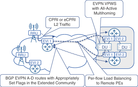
FIGURE 8.12 EVPN Point-to-Point Service
Although the original EVPN standard describes only the MPLS-based forwarding plane, the EVPN VPWS RFC also mentions the virtual eXtensible local area network (VXLAN) as a forwarding mechanism alternative to MPLS. In fact, the EVPN control plane is becoming increasingly common in most VXLAN implementations.
VXLAN
In parallel to EVPN development, network architects were also trying to solve the challenges of L2 connectivity in the growing DC, as was mentioned in previous chapter. Proliferation of virtualization techniques pushed the number of individual MAC addresses in a typical DC far beyond the numbers of physical servers. Within a typical server, multiple tenants or virtual machines (VMs) use their own MAC addresses, which exacerbated the already serious scalability challenge for the L2-based DC networks of the time. The use of 802.1Q VLAN tagging offered temporary relief by providing flow isolation across DC tenants, but the number of VLANs required to support the growing number of DC tenants greatly exceeded the hard limit of 4096 VLANs in a single-tagged 802.1Q frame. Moreover, purely Layer 2 connectivity models had to rely on Spanning Tree Protocol families to prevent L2 loops from occurring in the networks. An idea of creating an overlay network for L2 services by encapsulating them into a special header and transporting it over the underlying L3 transport network was proposed to solve these challenges. This solution became standardized as RFC 7348 and is known today as virtual eXtensible local area network (VXLAN).
In simple terms, VXLAN creates a multitude of non-overlapping overlay networks on the same IP-based underlay transport. VXLAN expands traditional VLANs to 16 million separate instances by using a 24-bit VXLAN network identifier (VNI) in its header. VNI is akin to an EVPN instance and effectively creates isolation for MAC addresses and VLANs used by different tenants not involved in direct communications. Besides the VNI, the VXLAN header contains flags and fields reserved for future use. An L2 frame received from an end device is appended with a VXLAN header and is then transported using a UDP datagram over an IP-based transport.
In order to perform all necessary encapsulations and decapsulations, edge network devices implement a VXLAN tunnel endpoint (VTEP). Typically, a single VTEP serves multiple VNIs originating or terminating on the single edge network device. VTEPs can also be implemented as a software function inside the hypervisor, providing VXLAN services directly to the hosted VMs, without the use of dedicated networking hardware.
The original VXLAN RFC mainly focuses on data plane forwarding and does not explicitly discuss control plane mechanisms. L2 frames for remote MAC addresses are encapsulated with an appropriate VXLAN header and sent toward a remote VTEP based on its IP address. Early VXLAN implementations required all VTEPs for the same VNI to be explicitly configured with each other’s IP addresses. This lack of a proper control plane defined in the VXLAN standard as well as the flood-and-learn approach significantly limited the scalability of the VXLAN solution. To remedy this, the network equipment vendors attempted to create custom automation tools for VXLAN deployment and management in large DC environments. Examples of such tools include Cisco’s Virtual Topology System (VTS) and Arista’s CloudVision eXchange (CVX).16, 17 Figure 8-13 illustrates the concepts of VXLAN.
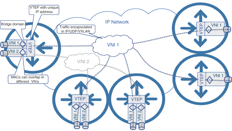
FIGURE 8.13 VXLAN Concepts
For BUM frames, two main options were defined:
The use of multicast for replication in the underlying transport network
Ingress replication of BUM frames and unicast delivery to all concerned remote VTEPs
Due to the lack of a control plane, BUM frame delivery is critical in the VXLAN’s flood-and-learn-based MAC-learning mechanism. The directly connected VTEP learns the MAC addresses of connected endpoints using a standard approach—by examining the source MAC addresses of L2 frames and populating the local MAC table. At the same time, for traffic forwarding, a lookup of the destination MAC address is performed in the local MAC table. If the destination is unknown, or a frame is sent to the multicast or broadcast MAC address, it is treated as a BUM frame and sent to all other VTEPs for the same VNI. Once this is received, the remote VTEP would learn the MAC addresses of the source, update its own MAC table, and use this information to unicast the return traffic to the originating VTEP.
While this process seems like basic Layer 2 switching, the critical difference in VXLAN is the routing of the encapsulated L2 frames over an IP underlay. With IP as the underlying transport, IP routing protocols could be used between Layer 3 switches implementing VTEPs and thus provide all the benefits of a robust Layer 3 transport, such as ECMP, L3 loop avoidance, and more.
Whereas VXLAN standards mostly cover data plane functionality, EVPN provides a comprehensive control plane for transporting Layer 2 frames over an MPLS-enabled forwarding plane. As both these technologies were being developed mostly in parallel, the networking industry quickly turned to augment the VXLAN solution with a BGP-based EVPN control plane. The standardization efforts to use EVPN as a control plane for forwarding planes other than MPLS resulted in IETF RFC 8365, “A Network Virtualization Overlay Solution Using Ethernet VPN (EVPN).”18 Although some EVPN-defined procedures and the use of messages and flags were adjusted to support non-MPLS forwarding planes, the main concepts, route types, and procedures remained mostly intact. When used with VXLAN, label fields in EVPN messages exchange information about VXLAN network identifiers, and VTEP IP addresses are used instead of PE addresses.
Today, Segment Routing MPLS-based DCs are growing in popularity, but many existing DCs still use VXLAN as their forwarding technology. By introducing scalable MAC-learning procedures via the EVPN control plane, VTEP auto-discovery and support of All-Active multihoming scenarios, in combination with VXLAN and EVPN, can offer the same level of service as MPLS-based EVPN.
