4.4 Stepper Control
Because VR steppers are so scarce, this section focuses on controlling PM and HY steppers, which are almost always two-phase motors. Some PM and HY steppers are bipolar and have four wires. Others are unipolar and have five or six wires.
The terms bipolar and unipolar identify how the wires are connected to the motor’s windings. Before you design a control circuit for a stepper, you should know whether it’s unipolar or bipolar as well as the difference between the two types. For this reason, the first part of this section discusses bipolar and unipolar steppers and how to control them.
The last part of this discussion presents different methods of delivering current to a stepper’s windings. These methods include half-stepping, which improves angular resolution but reduces torque, and microstepping, which improves angular resolution even further.
4.4.1 Bipolar Stepper Control
A two-phase bipolar stepper has four wires. Figure 4.10 shows how they’re connected inside the stepper.
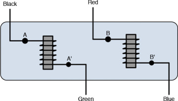
Figure 4.10 Connections of a bipolar stepper
This figure depicts electromagnets and their corresponding phases: A/A’ and B/B’. As explained in Chapter 3, “DC Motors,” the electromagnet’s poles are determined by the nature of the current flow. If current flows from the black wire to the green wire, A will be the north pole and A’ will be the south pole. If current flows from green to black, A will be the south pole and A’ will be the north pole.
Figure 4.10 identifies the colors of the wires entering the stepper, but these aren’t set by any standard. Instead, they follow a convention I’ve encountered in many bipolar steppers. If you find a stepper whose wires have different colors, the first place to look is the stepper’s datasheet. If this doesn’t help, you can test the wires with an ohmmeter—the resistance between A and A’, like that between B and B’, is very small. The resistance between wires in different phases is very high.
To design a circuit that drives a bipolar stepper, you need a means of reversing current in the wires. A common method of accomplishing this involves using H bridges, which were introduced in Chapter 3. An H bridge consists of four switches that, when opened and closed properly, make it possible to deliver current in the forward and reverse directions.
Figure 4.11 shows how an H bridge can be connected to control one phase (A/A’) of a bipolar motor. This uses four MOSFETs to serve as the switches.
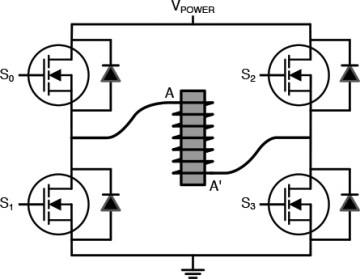
Figure 4.11 Controlling one phase of a bipolar stepper with an H bridge
The current’s direction is controlled by setting voltages on the MOSFET gates. When S0 and S3 are set high and S1 and S2 are low, current travels from A to A’, making A the north pole and A’ the south pole. When S1 and S2 are set high and S0 and S3 are low, current travels from A’ to A, making A’ the north pole and A the south pole. When S0 and S2 are left low, the winding is unenergized.
Chapter 9, “Motor Control with the Arduino Mega,” and Chapter 10, “Motor Control with the Raspberry Pi,” explain how stepper motors can be controlled with real-world circuitry. In both cases, the control circuit contains two H bridges capable of governing both phases of a bipolar stepper motor.
4.4.2 Unipolar Stepper Control
The wiring of a unipolar stepper motor is more complicated than that of a bipolar motor, but the goal is the same: to energize A, A’, B, and B’ and to set their north/south poles accordingly. To understand how this is done, consider the two circuits depicted in Figure 4.12.
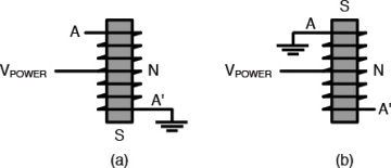
Figure 4.12 Electromagnet circuits with a center tap
In both figures, VPOWER is connected to the center of the electromagnet’s winding. This type of connection is called a center tap.
In Figure 4.12a, the bottom of the winding is connected to ground. Current flows from the center to ground, energizing the electromagnet and making the bottom of the winding (labeled A’) the south pole. The north pole is located at the center.
Now here’s the tricky part: The top of the winding isn’t connected to anything, so no current flows from the top of the winding to the center. However, the entire iron core is magnetized by the current in the lower wire, which means that the top of the winding also behaves as the electromagnet’s north pole. Therefore, in Figure 4.12a, A is north and A’ is south.
Figure 4.12b illustrates the reverse situation. The top of the winding is connected to the ground, so current flows from the winding’s center to the top. This makes the top of the winding (A) the south pole and the center of the winding the north pole. Because the entire iron core is magnetized, the bottom of the winding (A’) also behaves as the north pole.
From a circuit designer’s perspective, controlling a two-phase unipolar stepper requires three steps:
- Provide VPOWER to the A/A’ and the B/B’ windings.
- For each winding, connect one wire to ground to set the magnetic poles.
- Leave other wires unconnected.
Figure 4.13 depicts the six wires entering the unipolar stepper: two carry power (VPOWERA and VPOWERB) and four are connected to A, A’, B, or B’. Each of the latter four wires is connected to a MOSFET. When the MOSFET’s gate voltage exceeds its threshold, the wire is connected to ground. Otherwise, the wire is left unconnected.
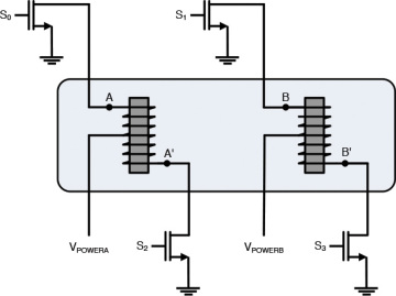
Figure 4.13 Connections of a unipolar stepper
When a MOSFET switches on, the corresponding end of the winding becomes the south pole. The opposite end of the winding becomes the north pole. For example, when voltage is applied to S1, the resulting current makes B the south pole and B’ the north pole.
Many unipolar steppers have five wires instead of six. For these motors, the two supply wires, VPOWERA and VPOWERB, are connected together. The other four wires remain unchanged.
Unipolar steppers are easier to control than bipolar steppers because there’s no need to manage the switches of two H bridges. However, when a unipolar stepper is energized, only half of the electromagnet is used. Therefore, if a unipolar stepper and a bipolar stepper have the same windings, the unipolar stepper will be half as efficient. This is why I recommend using bipolar steppers whenever possible.
If you ignore the VPOWER wires of a unipolar stepper, you can deliver current directly between A and A’ and between B and B’. In essence, this is driving a unipolar stepper as a bipolar stepper.
I’d like to make one last point concerning unipolar and bipolar steppers. If you look at a stepper’s datasheet, the wiring diagrams won’t look like the diagrams presented in this chapter. They represent windings using simpler symbols, and Figure 4.14 shows a sample diagram for a bipolar stepper and a unipolar stepper.
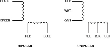
Figure 4.14 Sample wiring diagrams in a stepper datasheet
Like many datasheets, this figure doesn’t identify which winding is A/A’ and which is B/B’. This isn’t a significant concern. If you replace A/A’ with B/B’ in a control sequence, the motor’s rotation won’t be seriously affected.
4.4.3 Drive Modes
This chapter has explained how to operate steppers by energizing one or two winding pairs at a time, but there are a number of different ways to drive a stepper, and this discussion touches on four of them:
- Full-step (one phase on) mode—Each control signal energizes one winding.
- Full-step (two phases on) mode—Each control signal energizes two windings.
- Half-step mode—Each control signal alternates between energizing one and two windings.
- Microstep mode—The controller delivers sinusoidal signals to the stepper’s windings.
Choosing between these modes requires making tradeoffs involving torque, angular resolution, and power.
Full-Step (One Phase On) Mode
The simplest way to control a stepper is to energize one winding at a time. This is the method discussed at the start of this chapter. Figure 4.15 shows what the signaling sequence looks like when controlling a stepper in this mode.
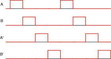
Figure 4.15 Drive sequence in full-step (one phase on) mode
With each control signal, the rotor turns to align itself with the energized winding. The rotor always turns through the stepper’s rated step angle. That is, if a PM motor is rated for 7.5°, each control signal causes it to turn 7.5°.
Full-Step (Two Phases On) Mode
In the full-step (two phases on) mode, the controller energizes two windings at once. This turns the rotor through the stepper’s rated angle, and the rotor always aligns itself between two windings. Figure 4.16 illustrates one rotation of a stepper motor driven in this mode.
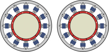
Figure 4.16 Stepper rotation in full-step (two phases on) mode
Figure 4.17 shows what the corresponding drive sequence looks like.
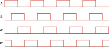
Figure 4.17 Drive sequence in full-step (two phases on) mode
The main advantage of this mode over full-step (one phase on) is that it improves the motor’s torque. Because two windings are always on, torque increases by approximately 30%–40%. The disadvantage is that the power supply has to provide twice as much current to turn the stepper.
Half-Step Mode
The half-step mode is like a combination of the two full-step modes. That is, the controller alternates between energizing one winding and two windings. Figure 4.18 depicts three rotations of a stepper in half-step mode.
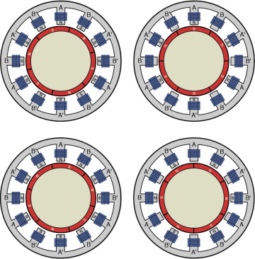
Figure 4.18 Stepper rotations in half-step mode
Figure 4.19 illustrates a control signal for a stepper motor driven in half-step mode.
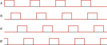
Figure 4.19 Drive sequence in half-step mode
In this mode, the rotor aligns itself with windings (when one winding is energized) and between windings (when two windings are energized). This effectively reduces the motor’s step angle by half. That is, if the stepper’s step angle is 1.8°, it will turn at 0.9° in half-step mode.
The disadvantage of this mode is that, when a single winding is energized, the rotor turns with approximately 20% less torque. This can be compensated for by increasing the current.
Microstep Mode
The purpose of microstep mode is to have the stepper turn as smoothly as possible. This requires dividing the energizing pulse into potentially hundreds of control signals. Common numbers of division are 8, 64, and 256. If the energizing pulse is divided into 256 signals, a 1.8° stepper will turn at 1.8°/256 = 0.007° per control signal.
In this mode, the controller delivers current in a sinusoidal pattern. Successive windings receive a delayed version of this sinusoid. Figure 4.20 gives an idea of what this looks like.
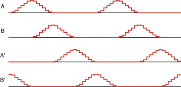
Figure 4.20 Drive sequence in microstep mode
Using this mode reduces torque by nearly 30%, but another disadvantage involves speed. As the width of a control signal decreases, the ability of the motor to respond also decreases. Therefore, if the controller delivers rapid pulses to the stepper in microstep mode, the motor may not turn in a reliable fashion.

