This chapter is from the book
This chapter is from the book
This chapter is from the book
19.4 Other Flow Situations
19.4.1 Flow Past Submerged Objects
Objects moving in fluids and fluids moving past stationary, submerged objects are similar situations that are described by the force balance. When an object is released in a stationary fluid, it will either fall or rise, depending on the relative densities of the object and the fluid. The object will accelerate and reach a terminal velocity. The period of acceleration is found through an unsteady-state force balance, which is
)
where ρs is the object density, and ρ is the fluid density. For solid objects, the density difference most likely will be positive, so the object moves downward due to gravity and the drag force resists that motion—hence the opposite signs of the two terms on the right-hand side of Equation (19.36). However, for a gas bubble in a liquid, for example, the density difference is negative, so the bubble rises and the drag force resists that motion. Since velocity is generally defined as being positive moving away from gravity, because that is the positive direction of the coordinate system, the signs reconcile.
For a sphere, the mass is
)
where Ds is the sphere diameter, and the volume is defined in Equation (19.37). The drag force on an object is defined as
)
where CD is a drag coefficient that may be thought of as an analog to the friction factor, Aproj is the projected area normal to the direction of flow, and u is the velocity of the object relative to the fluid. For a sphere, the projected area is that of a circle, as shown in the second equality of Equation (19.38). For a cylinder with transverse flow, this area is that of a rectangle. Equation (19.37), Equation (19.38), and the volume of a sphere may be substituted into Equation (19.36), and integration between the limits of zero velocity at time zero and velocity u at time t yields the transient velocity. The transient velocity approaches the terminal velocity at t → ∞, which can also be obtained by solving for velocity in Equation (19.36) when du/dt = 0, that is, at steady state, when the sum of the forces on the object equal zero. The terminal velocity is
)
An expression for the drag coefficient is now needed, just as an expression for the friction factor was needed for pipe flow. Similar to pipe flow, there are different flow regimes with different drag coefficients. The Reynolds number for a sphere is defined as Re = Dsut ρ/μ, where the density and viscosity are always that of the fluid, and if Re << 1, which is called creeping flow, this is the Stokes flow regime. Stokes’ law, which is a theoretical result, states that the drag force in Equation (19.36) is defined as
)
which yields
)
Stokes’ law must be applied only when it is valid, even though its use makes the mathematical results much simpler. In addition to the Reynolds number constraint, the assumptions involved in Stokes’ law are a rigid sphere and that gravity is the only body force. An example of another body force is electrostatic force; therefore, Stokes’ law may fail for charged objects. Theoretically, there are two drag force components for flow past an object. This is based on the concept that drag is manifested as a pressure drop. Form drag is caused by flow deviations due to the presence of the object. Since the fluid must change direction to flow around the object, energy is “lost,” which is manifested as a pressure drop. Frictional drag is analogous to that in a pipe and is due to the contact between the fluid and the object. In Equation (19.40), two-thirds of the total is due to frictional drag and one-third is due to form drag.
Experimental data are usually used as a means to determine the drag coefficient. There are curve fits for the intermediate region, between creeping flow and the constant value observed for 1000 < Re < 200,000. Haider and Levenspiel [11] provide a curve fit to the data for all values of Re < 200,000:
)
and these results are plotted in Figure 19.8.
)
Figure 19.8 Drag Coefficient Dependence on Reynolds Number; the Dotted, Straight Line Is the Creeping Flow Asymptote (From Haider, A and O. Levenspiel, “Drag Coefficient and Terminal Velocity of Spheres and Nonspherical Particles,” Powder Technol. 58 (1989): 63–70, Equation [19.42])
Equation (19.42) is not convenient for solving the terminal velocity of a sphere falling in a fluid because an iterative solution is required (see Example 19.11). However, this equation may be reformulated in terms of two other dimensionless variables,  and D*:
)
)
and
)
If the properties of the fluid and particle are known, then D* can be calculated using Equation (19.44), and then Equation (19.45) can be used to determine , and finally ut can be calculated from Equation (19.43). This is illustrated in Example 19.11.
Example 19.11
In a particular sedimentation vessel, small particles (SG = 1.2) are settling in water. The particles have a diameter of 0.2 mm. What is the terminal velocity of the particles?
Solution
Since the particles are small, creeping flow will be assumed initially. Substituting Equation (19.41) into Equation (19.39) yields
)
Checking the Reynolds number,
)
which is not in the creeping flow regime. Therefore, simultaneous solution of Equations (19.39) and (19.42) is required, and the result is ut = 0.0039 m/s and Re = 0.78.
Alternatively, using Equations (19.43), (19.44), and (19.45),
)
)
)
For Re > 2 × 10⁵, the phenomenon called boundary layer separation occurs. The drag coefficient in this region is CD = 0.22.
With the exception of the boundary layer separation region, Figure 19.8 has about the same shape as Figure 19.6. For low Reynolds numbers, the friction factor and drag coefficient are both inversely proportional to the Reynolds number, though the exact proportionality is different. For large Reynolds numbers, what is generally called fully turbulent flow, the friction factor and drag coefficient both approach constant values.
For nonspherical particles, the determination of the drag coefficient and terminal velocity is more complicated. A major challenge is how to account for particle shape. One method is to define the shape in terms of sphericity. Sphericity is defined as
)
Then, the diameter of a sphere with the same volume as the particle, dv, is calculated and used in place of the diameter in Equations (19.37) through (19.42). Care is needed when using sphericity, since particles with quite different shapes but similar sphericities may behave quite differently when falling in a fluid.
Example 19.12
Determine the sphericity and Dv of a cube.
Solution
Call the dimension of the cube x. Therefore, Dv is obtained from
)
)
and the sphericity is
)
Haider and Levenspiel (1989) have provided a curve fit for previously published experimental data, which were taken for regular geometric shapes. The drag coefficient for different sphericities is illustrated in Figure 19.9, and the curve-fit equation is
)
)
Figure 19.9 Drag Coefficient Dependence on Reynolds Number and Sphericity from Haider and Levenspiel (1989), Equation (19.47)
 .
.
The equivalent expression in terms of D* and ut* is given as
)
where Dv is the diameter of a sphere with the same volume as the particle.
Equation (19.39) can be solved for one unknown by using either Equation (19.41) or Equation (19.42) for the drag coefficient. For example, the viscosity of a fluid can be determined by measuring the terminal velocity of a falling sphere. Or, the terminal velocity of an object can be determined if all of the fluid and particle physical properties are known. If the Reynolds number is unknown, then the flow regime is unknown. Therefore, depending on the type of problem being solved, judgment may be needed to assume a flow regime, the assumption must be checked, and iterations may be required to get the correct answer.
19.4.2 Fluidized Beds
If fluid flows upward through a packed bed, at a high enough velocity, the particles become buoyant and float in the fluid. For this condition, the upward drag on the particles is equal to the weight of the particles and is called the minimum fluidization velocity, and the particles are said to be fluidized. This is one reason why flow through packed beds is usually downward. The benefits of fluidization are that once the particles are fluidized, they can circulate and the bed of solids mixes. If the upward fluid velocity is sufficiently high, then the bed of particles becomes well mixed (like a continuous stirred tank reactor) and approaches isothermal behavior. For highly exothermic reactions, this property is very desirable. Fluidized beds are often used for such reactions and are discussed in Chapter 22, “Reactors.” Fluidized beds are also used in drying and coating operations where the movement of solids is desirable to increase heat and/or mass transfer. As the fluid velocity upward through the bed of particles increases, the mixing of particles becomes more vigorous and there is a tendency for particles to be flung upward and elutriate from the bed. Therefore, a cyclone is typically part of a fluidized bed to remove the entrained particles and recirculate them to the fluidized bed. Another desirable feature of fluidized beds is that they can be used with very small catalyst particles without a large pressure drop. For very small catalyst particles in a packed bed, the pressure drop becomes very large. An example of such a catalyst is the fluid catalytic cracking catalyst used in petroleum refining to make smaller hydrocarbons from large ones.
The general shape of the pressure drop versus superficial fluid velocity in a fluidized bed is shown in Figure 19.10.
)
Figure 19.10 Plot Illustrating Constant Value of Pressure Drop above Minimum Fluidization Velocity
The region to the left of umf is described by the Ergun equation for packed beds because, before fluidization begins, behavior is that of a packed bed. If the particles were restricted, by, say, placing a wire screen on top of the bed, then the bed would continue to behave as a packed bed beyond the umf. Assuming that the top of the bed is unrestricted, once there is sufficient upward velocity, and hence upward force, the particles begin to lift. This is called minimum fluidization. At minimum fluidization, the upward force is equal to the weight of the particles. Hence, the frictional force equals the weight of the bed, and the pressure drop remains constant. Quantitatively,
)
where the subscript mf signifies minimum fluidization and hmf is the height of the bed at minimum fluidization, which for a packed bed is called the length of the bed, L. At the instant at which fluidization begins, the frictional pressure drop is equal to that of a packed bed. Combining Equation (19.19), which is the frictional loss in a packed bed and equals −ΔPfr/ρ, and Equation (19.49) yields
)
Rearranging Equation (19.50) and defining two dimensionless groups that characterize the fluid flow in a fluidized bed,
)
)
where Equation (19.51) is the particle Reynolds number, which characterizes the flow regime, and Equation (19.52) defines the Archimedes number, which is the ratio of gravitational forces/viscous forces, yields
)
Equation (19.53) is a quadratic in Remf, so the minimum fluidization velocity can be obtained if the physical properties of the solid and fluid are known. For nonspherical particles, the result is
)
If the void fraction at minimum fluidization, which must be measured, and/or the sphericity are not known, Wen and Yu [12] recommend using
)
)
and Equation (19.54) reduces to
)
Since the volume of solid particles remains constant, it is possible to relate the bed height and void fraction at different levels of fluidization.
)
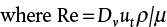
Equation (19.58) is understood by multiplying each side of the equation by At, the total bed area, so each side of the equation is the volume of particles because (1 − ε) is the solid fraction, and hAt is the total bed volume. The operation of fluidized beds above umf varies considerably on the basis of the size of particles and the superficial velocity of gas. One way to describe the behavior of these beds is through the flow map by Kunii and Levenspiel [13] in Figure 19.11. In Figure 19.11, u* and D* refer to the dimensionless velocity and particle size introduced in Section 19.4.1, except that the superficial velocity of the gas through the bed (not the particle terminal velocity) is used in u*.
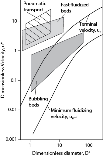
Figure 19.11 Flow Regime Map for Gas−Solid Fluidization (Modified from Kunii, D., and O. Levenspiel, Fluidization Engineering, 2nd ed. [Stoneham, MA: ButterworthHeinemann, 1991])
It is clear from this figure that operation of fluidized beds can occur over a wide range of operating velocities from umf to several times the terminal velocity. For turbulent (lying above bubbling beds) and fast fluidized beds, internal and external cyclones must be employed, respectively. The gas and solids flow patterns in all these regimes are very complex and can be found only by experimentation or possibly by using complex computational fluid dynamics codes.
19.4.3 Flowrate Measurement
The traditional method for measuring flowrates is to add a restriction in the flow path and measure the pressure drop. The pressure drop can be related to the velocity and flowrate by the mechanical energy balance. More modern instruments include turbine flow meters that measure flowrate directly and vortex shedding devices.
The types of restrictions used are illustrated in Figure 19.12.
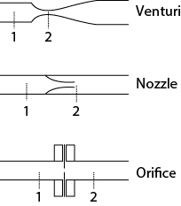
Figure 19.12 Typical Devices Used to Measure Flowrate
The control volume is fluid between an upstream point, labeled 1, and a point in the obstruction, labeled 2. For turbulent flow, the mechanical energy balance written between these two points is
)
The friction term is dropped at this point but is incorporated into the problem through a discharge coefficient, Co. From Equation (19.3), u1 is expressed in terms of u2, the cross-sectional areas, and then the diameters; solving for the velocity in the obstruction yields
)
where
)
The flowrate can then be obtained by multiplying the velocity in the restriction by the cross-sectional area of the restriction. The term Co, a discharge coefficient, is added to account for the frictional loss in the restriction. Figure 19.13 shows Co as a function of β and the bore (restriction) Reynolds number for an orifice, one of the most common restrictions used. Since Co is not known, the asymptotic value of 0.61 for high-bore Reynolds number is assumed, and iterations may be required if the bore Reynolds number is not above about 20,000. This calculation method is illustrated in Example 19.13.
)
Figure 19.13 Orifice Discharged Coefficient (From Miller, R. W., Flow Measurement Engineering Handbook [New York: McGraw−Hill, 1983] [14])
Other flow measurement devices are used. One such device is the rotameter that has a float that moves within a variable area vertical tube. The level of the float in the device is related to the flowrate, as illustrated in Figure 19.14. As the fluid flow increases, the drag on the float increases and it moves up, but the annular flow area around the float also increases. Consequently, the float comes to a new equilibrium position at which its weight is just balanced by the upward drag force of the fluid. Rotameters are still found in laboratories and provide accurate measurements for both gas and liquid flows. While there is a theoretical description of how a rotameter works, it is typically calibrated by measuring the flowrate versus the height of the float for the given fluid of interest.
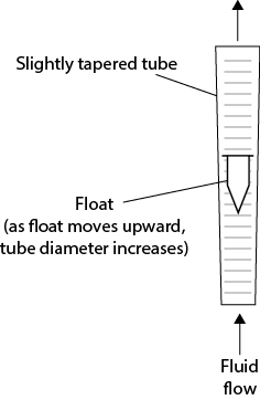
Figure 19.14 Illustration of Rotameter
Measuring pressure differences is automated in a chemical plant through the use of various devices. However, manometers may still be found in laboratories. Manometers work by having an immiscible fluid of higher density than the flowing fluid in a U-shaped tube, with one end of the tube connected to the pipe at Location 1 and the other end connected as close as possible to Location 2. The height difference between the levels of the immiscible fluid is a measure of the pressure difference between Locations 1 and 2. Figure 19.15 illustrates a general manometer, where the pipe in which the fluid is flowing may be inclined.
)
Figure 19.15 Illustration of General Manometer Situation
The manometer is an example of fluid statics, so the pressure at any horizontal location must be the same in each manometer leg. For the pressure at height 3 in Figure 19.15,
)
Equation (19.62) can be rearranged into the “general” manometer equation:
)
where
)
The third term in Equation (19.63) is zero if the pipe is horizontal. It is important to understand that z1 − z2 is a difference in vertical distance (height), not a distance along the pipe, and that the coordinate system points upward, so a high height minus a low height is a positive number.
Example 19.13
An orifice having a diameter of 1 in is used to measure the flowrate of an oil (SG = 0.9, μ = 50 cP) in a horizontal, 2-in, schedule-40 pipe at 70°F. The pressure drop across the orifice is measured by a mercury (SG = 13.6) manometer, which reads 2.0 cm. Calculate the volumetric flowrate of the oil.
Solution
Two steps are involved. First, the pressure drop is calculated from the manometer information. Then, the flowrate is calculated.
To calculate the pressure drop, Equation (19.62) is used, but since the pipe is horizontal, the third term on the right-hand side is zero. The result is
)
Next, the pressure drop is used in Equation (19.60) with the initial assumption that Co = 0.61. So
)
Now, the bore Reynolds number must be checked.
)
From Figure 19.13, with β = 0.48 and Re = 749, Co ≈ 0.71. Repeating the calculation in Equation (E19.11b) gives u2 = 5.63 ft/sec and Re = 872. Within the error of reading Figure 19.12, Co ≈ 0.71, so the iteration is completed. The volumetric and mass flowrates can now be calculated:
)
)
When fluid flows through an orifice, the pressure decreases because the velocity increases through the small cross-sectional area of the orifice. Physically, this is because pressure energy is converted to kinetic energy. This is similar to a nozzle, as illustrated in Example 19.3. Subsequently, when the velocity decreases as the cross-sectional area increases to the total pipe area, the pressure increases again. However, not all of the pressure is “recovered,” due to circulating fluid flow at the pipe-orifice diameter. The permanent pressure loss requires incremental pump power, and that is part of the cost of measuring the flowrate using an orifice or nozzle. The amount of recovered pressure has been correlated as a function of β for different flow measuring devices, and it is illustrated in Figure 19.16.
)
Figure 19.16 Unrecovered Frictional Loss in Different Flow Measuring Devices (Adapted by permission from Cheremisinoff, N. P., and P. N. Cheremisinoff, Instrumentation for Process Flow Engineering [Lancaster: Technomic, 1987] [15])
Example 19.14
For Example 19.13, how much additional power is needed for the permanent pressure loss through the orifice? The pump is 75% efficient.
Solution
For β ≈ 0.5, from Figure 19.16, the permanent pressure loss is about 73%. From the mechanical energy balance,
)
)
so
)
)
)
)
)
)
)
)
)
)
)
This result shows that, while there is a cost associated with an orifice, it is small.